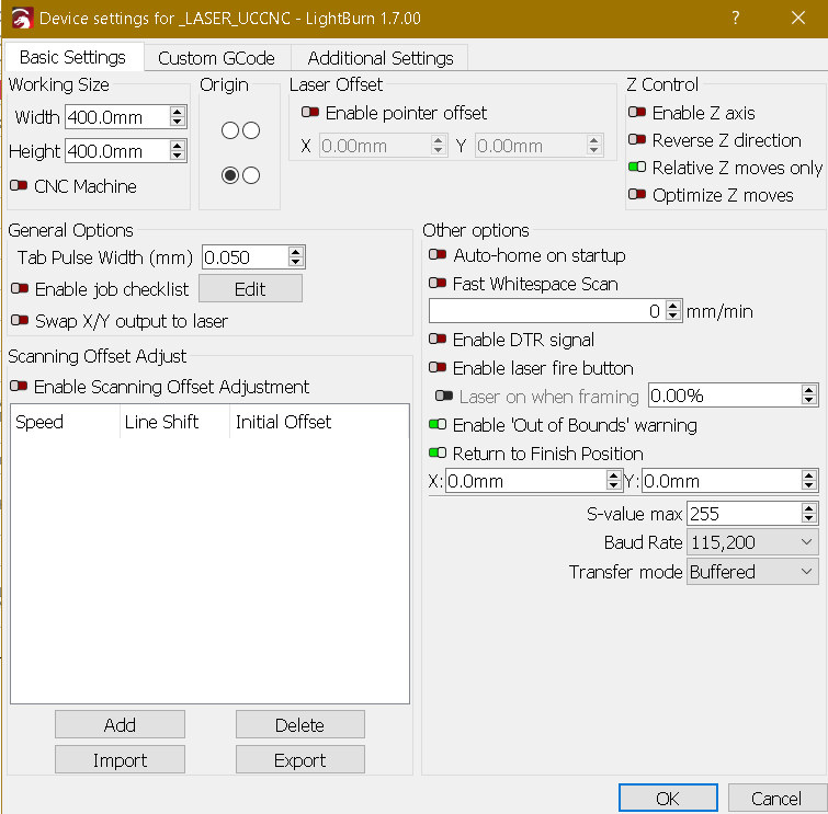
Good day to all fellow laser users, sorry for the lengthy post. I have been tackling a particular problem for a long while without any success in finding a solution even though I searched everywhere from this forum to YouTube.
Basic outline: my 130W laser is servo driven, using UCCNC software & hardware, so connecting directly to the machine is out of the question up to the recent Lightburn software 1.6.00. So I am transfering jobs by saving the GCode in Lightburn, using GRBL-M3 (the only one that currently works) and then using the UCCNC macro to import Lightburn exported GCode files.
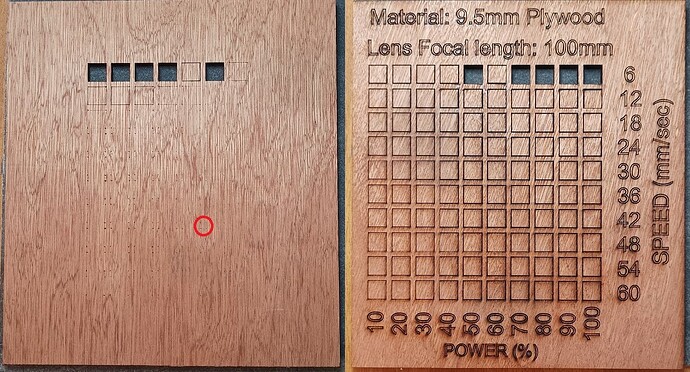
I have managed to get it to cut lines as they should but am having problems when the laser changes direction at corners where the laser beam is punching through the material even though at a relativly low power (see attached in red circle). From what I have read in many sources this is attributed to laser staying too long in the same place until it changes direction and the solution to this is to ramp down the laser power as it approaches the corner. I have tried many many settings but with no results.
The laser power is responding to the original lightburn settings, as I can see the current meter varing between one setting to another.
With this in mind, I narrowed it down to either (most likely) the GRBL code isn’t giving the proper instuctions related to rampming down or else there may be a fine tuning setting in Lightburn which I am not seeing or not aware of.
I have also compared GRBL codes in attempt to understand but unfortunately am comletely hopeless in this area. I mean, I see the difference from one to another (like M10 Q255 command) but have no clue how to put things together in this case. I have even tried reading tutorials in GRBL settings and tried cutting something but again failed!
Can anyone here advise if I’m making sense and maybe direct me in the right direction?
Much appreciated.
Marten
I’m, not really a grbl person, so …
Does you controller handle varying power on a corner? I have a dsp (Ruida) and it handles all of this, not Lightburn…
I thought this was handled by the controller, not Lightburn.
Maybe @misken can advise or one of the Lightburn folks - @Rick - which versions of grbl and if it’s a Lightburn function to do this…
Do you focus at the surface or middle of the material? I’d suggest material center with this kind of thickness… you’re only getting <4mm on each side from center of focus.
How is your cnc pwm wired to the lps (laser power supply)?
![]()
This is the culprit. grbl-m3 does not support dynamic power. It’s an older profile for earlier grbl-versions. Dynamic power, which automatically adjusts power to speed, was introduced in 1.1f (or so). If you select grbl-m3, then there is always constant power.
You are saying that it was the only thing that worked. Which error did you get? That M4 is a not supported command? Did you enable the laser mode setting ($32), that is required in that case, I think.
Hi Jack,
Since it varies the power from one line type to another, I suppose it should handle varying power at corners, that is why I concluded the problem is with the GRBL code. At this point in time I focus on the surface to avoid the possibility of having debris entering the lens area, but then again I wouldnt exclude focusing in the middle. Yes PWM is wired to the LPS.
Thanks
Hi Misken, yes GRBL-M3 is the only one that worked for me but as you said with constant power. When using 1.1f version the laser moves but doesn’t fire up. Have experimented with other GRBL codes and yes had errors but don’t remember what they were.
Also I do have a setting for M4 command but if this is what’s hindering me, am not sure to which pin I need to and port I need to set it - could it be the same pins of the PWM (picture below)?
Also I cannot enable $32 as the laser in not directly connected to Lightburn, this is why I save to GRBL GCode and then import it in UCCNC.
Thanks.
I have also been making comparisonsbetween the old (right) and new (left) versions of GRBL (as can be seen below) and have concluded that the code needs to have the M10 Q… command for the reason that both M3 and M4 are laser on / off switches as opposed to the M10 comand it is also a variable. Now my problem is how to incorporate, modify or create a GRBL Code that functions using the M10 Q… command.
Now that I am writing about this and to be completly honest, I havent tried using M4 instead of M3 as a setting. I will try setting pinouts of M3 on M4 export in the latest GRBL Code and see what happens. I dont have high hopes about the latter but its worth a try.
Sorry to step in.
M3(CW) and M4(CCW) on the CNC is different than on the laser M3(fixed power) and M4(dynamic power).
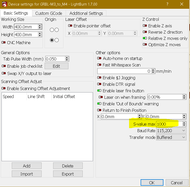
You could try a Custom GCode machine wit more options to adapt to your CNC, remember to set Lightburn S-value max to 255 because your controller only accept values between 0-255.
Check also if you have some setting for the PWM frequency as lot of laser modules usually work at 1000Hz.
Maybe you could create a UCCNC profile for laser and other for CNC so you don´t miss any settings.
Also you could read the following topic
.
You could try with your UCCNC laser plugin save the gcode of a small image and compare the output with the generated from Lightburn.
If the above solutions don’t work you have to save gcode and then edit with Notepad++ and auto replace commands per your machine requirements.
Hi Parsec, thanks for your input. Yes I do have separate profiles in UCCNC for both router and laser. Further more after having posted this and looking further into finding a solution, it dawned on me that the potential answer of setting M4 as the output instead of M3 was infront of me the whole time and you mentioning it affirmed that to me. As you clearly said M3 and M4 have different applications in laser and I was not looking at it that way and was simply dismissing it as using router CW / CCW as a means to only switch on laser!
At the moment I am bound inhouse due to a terrible cold I caught but as soon as it passes I’m gonna try it out.
Thanks
Hello to all,
Ok, so after having recuperated from the cold, I’ve had another go with the M4 settings on UCCNC and also tried one of the standard available GRBL GCodes on LightBurn. I then made a simple cutting profile and ran it on the laser but all it did was follow the cutting line without firing the laser ![]() . No errors just executed the movement.
. No errors just executed the movement.
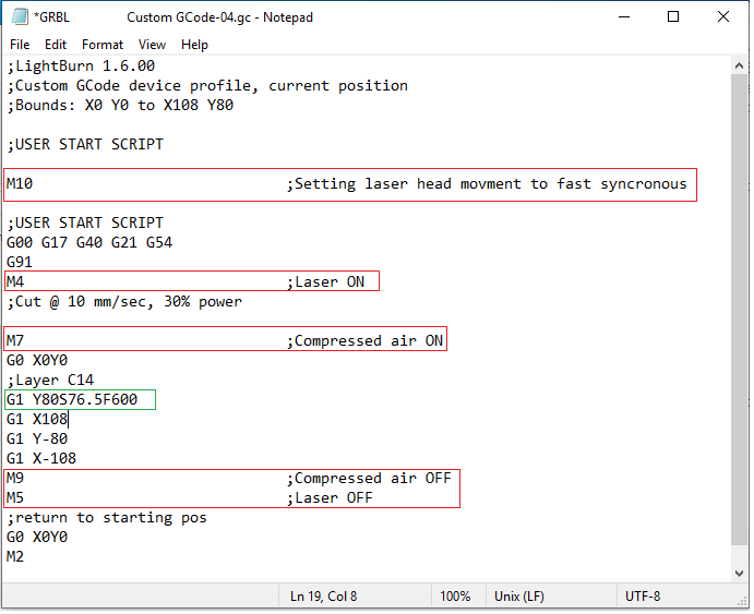
I then knew I needed to get my head wrapped around the GRBL language to at least have a functional code. So after a substantial amount of research I made a custom code (as parsec also advised - using the Smoothie flavour for a start), ran the same cutting file and came up with the below mentioned Gcode. I haven’t run it yet as I would like to see what you guys think about it and maybe be able to advise what might be a better code to use or even the order in which things are executed.
I have read somwhere on the forum that executing M10 before M4 will set the head to fast syncronous mode … I am not sure if this makes sense but I think this will conflict with G1 command. For sure will be doing away with the M7 and M9 comands since I run the compressor continuously the keep a clean lens.
Thanks Guys.
Regards
Marten
Ok, just some updates incase someone else should find himself in my shoes in the future.
So it seems that the Laserburn profile I created (and similar ones) have not worked at all. No errors given off in UCCNC, so I take it that the settings somewhat are interpreted correctly.
The results and outcome with the smoothie flavour I used are as follows:
1). I tried to cut a square and when Saving to GCode the geometry imported by UCCNC Lightburn Loader has distorted it to a house shape figure. Possible solution :- will be trying another flavour.
2). No errors raised by UCCNC and movement occurs with no problems what so ever.
3). Laser does not fire at all: Possible problem:- Incorrect settings in UCCNC or configuration of Lightburn profile somewhere about the M4, M10 and M3 code.
So far I have extensively experimented with combining M4 with M10, but honestly speaking cannot understand how to interpret the M10 code with the Q (or S) variable and also the settings in UCCNC where M10 settings are given in figures of M10.1, M10.2, M10.3 etc as seen below. Anyways, guess I need to further read, search and experiment furthermore!!! I do hope the light at the end of this tunnel isnt too far away!
I’ll keep posting about the progress made.
Thanks
I’m glad you’re feeling better.
I don’t know how, I didn’t see the previous post.
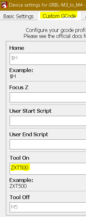
M4 won’t work, the idea is that when Lightburn applies M4 (in this example) we replace it in Custom Gcode with the code (example (ZXT500)
that works on our machine, so that Lightburn instead of M4 produces ZXT500 automatically and we can save the GCODE in a file we want to use directly.
That’s why I wrote to look at the output of the laser plugin so that you have a starting point know commands that work and connect the laser where it connects with the plugin.
Hi Parsec,
Sorry for not posting any earlier. I am so far going round in circles with the M4 and M10 Q … commands.
I am going to take a different approach, since my CNC worked with M3, except for the variable power, I will just be using the “Replace M3 with M4” option in UCCNC Lightburn loader v1.3, without M10 command and see if that works. I’m starting to think the same (that M4 doesn’t work) since the laser does not fire at all with no error warnings, so with the preceeding I will confirm that. If that would be the case I will have to consider other options trying to combine M3 with M10 Q…, whether that makes any sense I have no idea. As I said … I feel like a dog chasing its tail!! ![]()
Wish me luck!!
I believe with Ligtburn Custom GCode no need to use Lightburn Loader.
,
Check if this helps.
.
EDIT;
Try this files, no need to convert LOAD DIRECTLY with Laser plugin ( Absolute Coordinates, all power percent from 0-255) be prepared to TURN-OFF your machine if something goes wrong.
1= 1 shape
2=2 shapes
1_TEST_10power.gc (253 Bytes)
1_TEST_25power.gc (257 Bytes)
2TEST_10power.gc (382 Bytes)
.
Corresponding Lightburn files:
1_TEST_10power.lbrn2 (2.8 KB)
1_TEST_25power.lbrn2 (2.8 KB)
2TEST_10power.lbrn2 (10.0 KB)
.
Only if everything goes well remove .txt from the following Custom GCode Device file and import into Lightburn.
_Laser_UCCNC.lbzip.txt (1.5 KB)
After edit settings per your machine definitions.
.
.
Annotations:
- .You can set an Output pin (7) to PWM and obviously your controller can output a variable SET power, but I don´t know if your controller will manage/change the output power when direction in the path changes ( like in corners ). Maybe can better it a bit with some setting like $11.
- As a start solution for better output you can convert Lightburn shapes to bitmap and then laser it with your UCCNC laser plugin.
Hi Parsec,
Thanks for your help, I’ll view the links you provided and have a go at these files.
I’ll keep you posted.
Regards
Marten
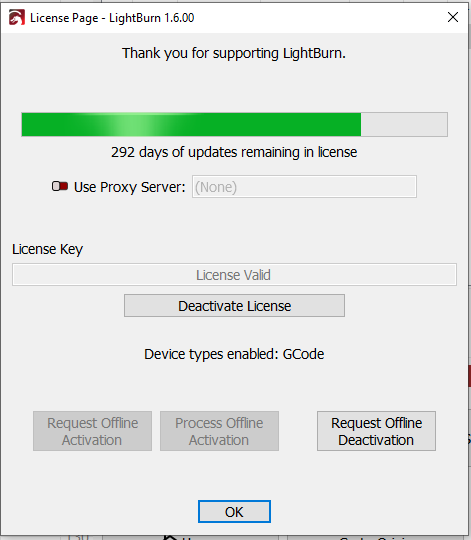
Question … I do hope I’m not running into another obstacle!! The files you sent are done in version 1.7.00 is that a beta version as my software (1.6.00) is saying that its’ up to date and still have 292 days for updates.
Thanks
Yes it is a beta version.
I believe 1.6.00 has similar or equal Custom Gcode.
Ha, thanks again … for a moment there I thought I had something was wrong with the sofware!! ![]()
Finally some progress, thanks to you, parsec, I feel releived! So, having checked out the links you provided confirmed that I had the settings in UCCNC correct. Further looking into the cutting files have mostly explained what I was doing wrong, although I still cannot wrap my head around the code itself and how to put one to another. Boy was I far away!!
Anyhow, I roughly adjusted the provided profile settings in Lightburn to fit my machine parameters, exported the gcode and opened it directly into UCCNC without the Lightburn loader, which I wouldn’t have ever imagined of doing that. Preliminary test run went smoothly without any issues, cutting path, laser firing & movement behaved as intended, while trying to keep an eye for current variations on the ammeter and it seems that there is. Naturally I need to do a more extensive trial runs and with broader range of speeds & power to finetune the firing and further confirm proper operation.
For now I will have to take some time off this matter as I am being called to visit our mother company in Germany, but upon returning I will be once again posting of progress being done, and naturally I will still be browsing around on the forum.
Thanks
Marteng
If you UCCNC needs the initial M05 add it after the M8 but always keep Air ON in Lightburn.
I never worked with UCCNC so you have to take a bit of trial and error.
Just a simple test you could design a rectangle e.g. 300mm x 5mm set the power a little lower than overburn for the test material and check if you get the corners burnt or the controller adapts speed/power.

Hi to all, so I got back and continued from where I left regarding this subject and have managed to further test, modify and retest with settings with some slight reduction in puncuring though at corners. This after having set the Lightburn profile to Variable Power and Enable Q-Pulse option and setting UCCNC to Constant velocity mode. I guess now I have ot set the minimum power setting in UCCNC to maybe see further improvements.
Since this has taken quite some time, I will do some cutting on some designs I did to see if I really need to either pursue this more or if these setting satisfy my design finish requirements. Time will tell!!
I have also managed to work with the M4 command, which is positive to know that the settings in UCCNC for that are correct enough to run.
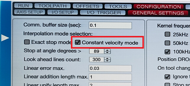
I would be posting of my results so as to leave some reference for others to come and also would like to thank all of you guys for pointing me in the right direction … I would probably be totally bald buy now pulling on my hair if it wasn’t for your support.
