You need to determine what voltage it operates. If there are no markings, then try at 5V, if it doesn’t work find the next voltage up, like 24V.
If possible find some information on what it needs, so you don’t damage it.
![]()
You need to determine what voltage it operates. If there are no markings, then try at 5V, if it doesn’t work find the next voltage up, like 24V.
If possible find some information on what it needs, so you don’t damage it.
![]()
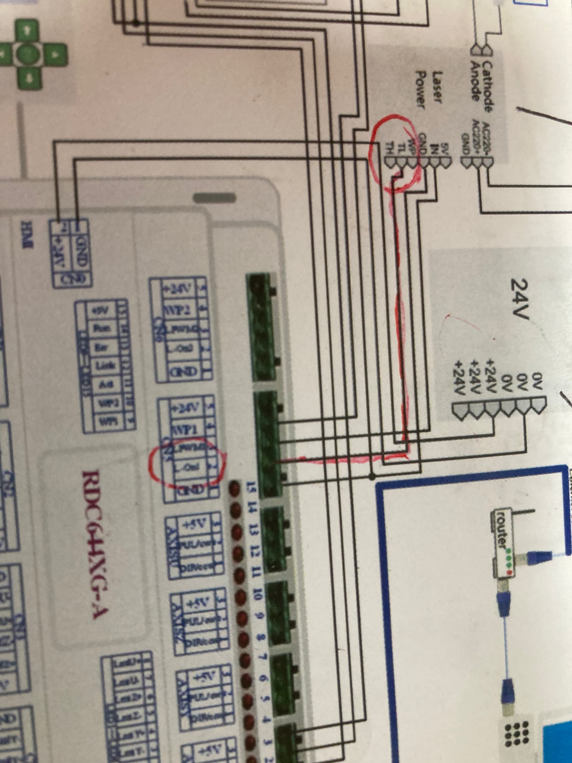
a question about theory… does the dash control panel and buttons control anything other than movement? does it control laser power at all? I dont see any wiring that goes from the panel to the ruida other than the motor controls.
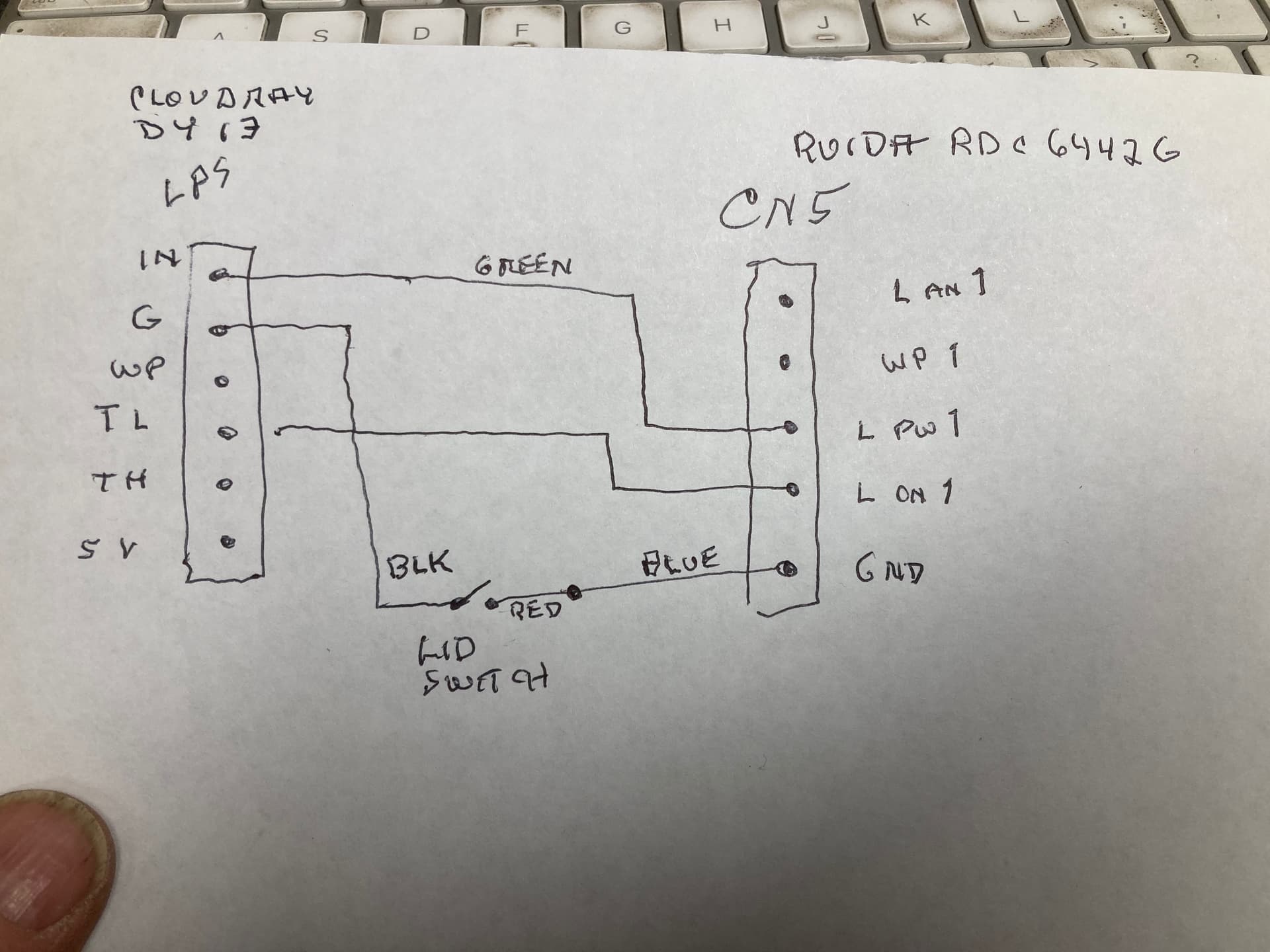
I think we went over this about two weeks ago… ![]()
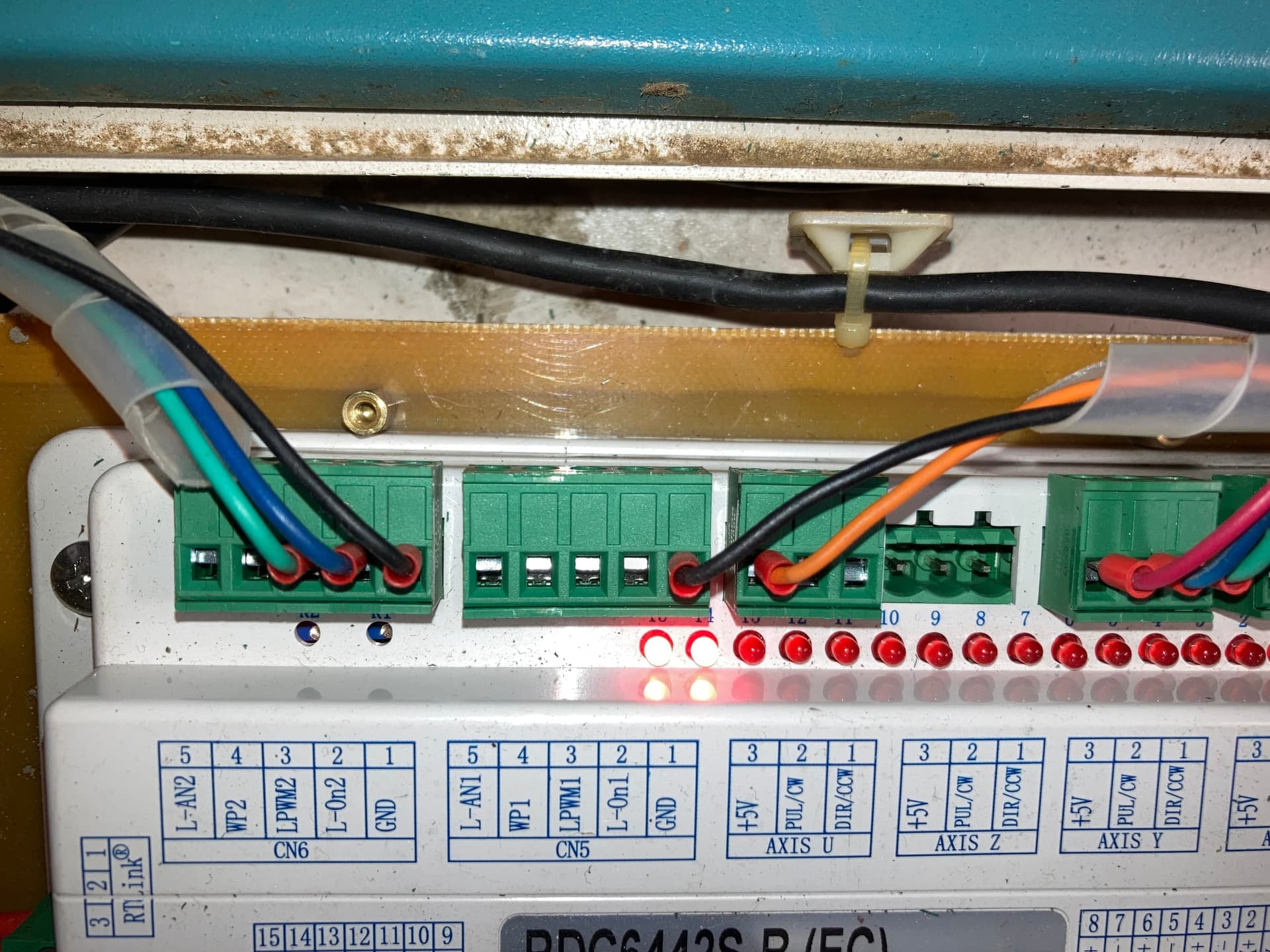
From your # 9 post, this photo shows your machine is wired to CN6 (laser 2) instead of CN5 (laser 1). Just swap the two connectors and it should work using laser one settings.
Black wires only, are both at ground level, so you can swap those between the connectors if you need too.
![]()
Jack, thanks for the reply. the way I had it wired did not match your little chart here so I changed things so it is like you show. as of today March 22 here is how I have things wired . before I changed the wiring I though I would test to see if the laser fired and all I did was press the top door close switch and it fired so I quit because that meant some how I had it wired wrong. This has to be something simple now as we are down to almost everything working
Lets clarify how these work. For a module to control another module, they speak over signals. What makes a useful signal is it’s reference. This is the ground connection. Last thing you want to do is to removed the ground on modules that depend on the signals. When you remove ground, you place the electronics in an unknown condition.
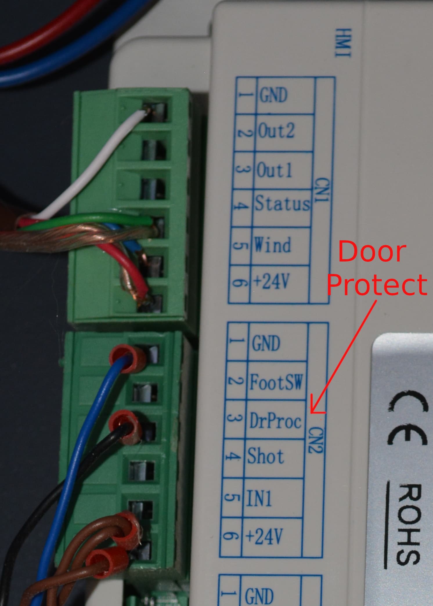
If you wish to use the door protect on your machine, wire it up to the door protection input of the Ruida CN2-3 (DrProc).
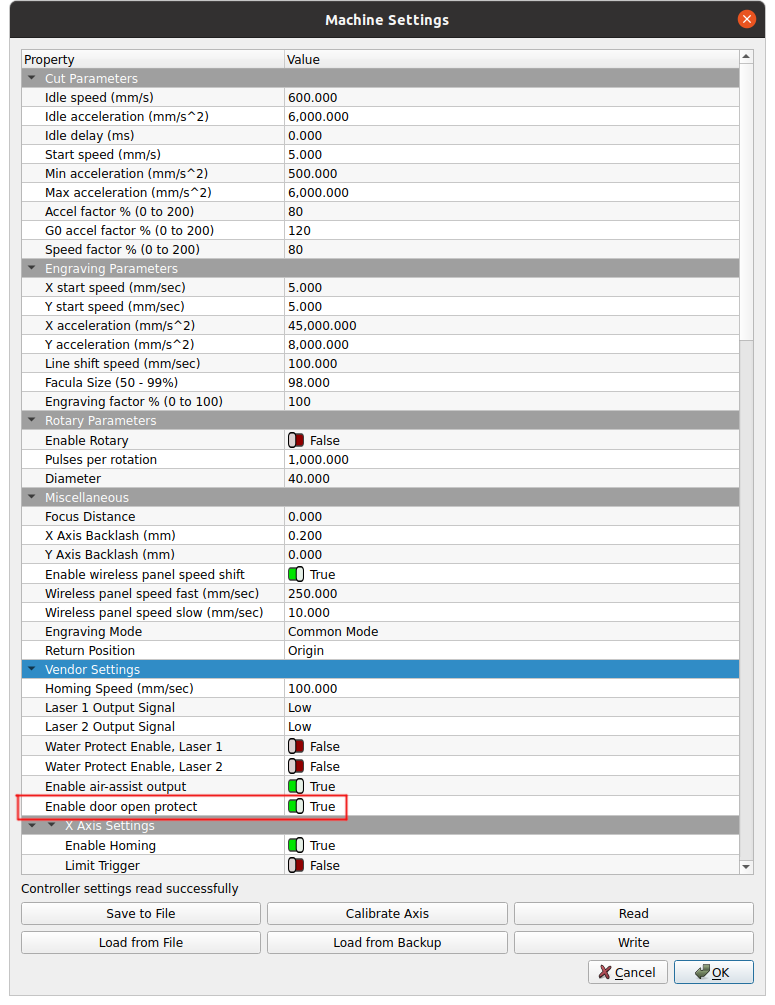
It has to be enabled in the Ruida.
The previous photo showed both black wired to ground, now you’ve re-wired it with one of the black wires going to L-On1? The lps shows no connection to wp input?
You might be smart to re-read some of what was posted.
![]()
OK,
The controller normally pulls TL low, so I’d say use the L input, then there’s not issue with changing the controllers output.
This would indicate the controller thinks all is OK, but there is a problem with how you’ve wired the L and IN inputs to the Ruida.
Can you confirm how these are wired?
There is a bit of two different ideas here.
If two modules are speaking with each other, you need something relative to the signal to be able to talk to the other module. We use a ground as a common or 0 point when we measure, generally speaking.
Don’t confuse that with the output signal levels that complete a ground to turn on something. Most of the Ruida inputs, stock configuration, also need to be pulled to ground.
Don’t let that slow you down, you’re doing fine and you seem to be picking up most of what I’ve spewed out. lol…
Hang in there and we’ll figure it out.
![]()
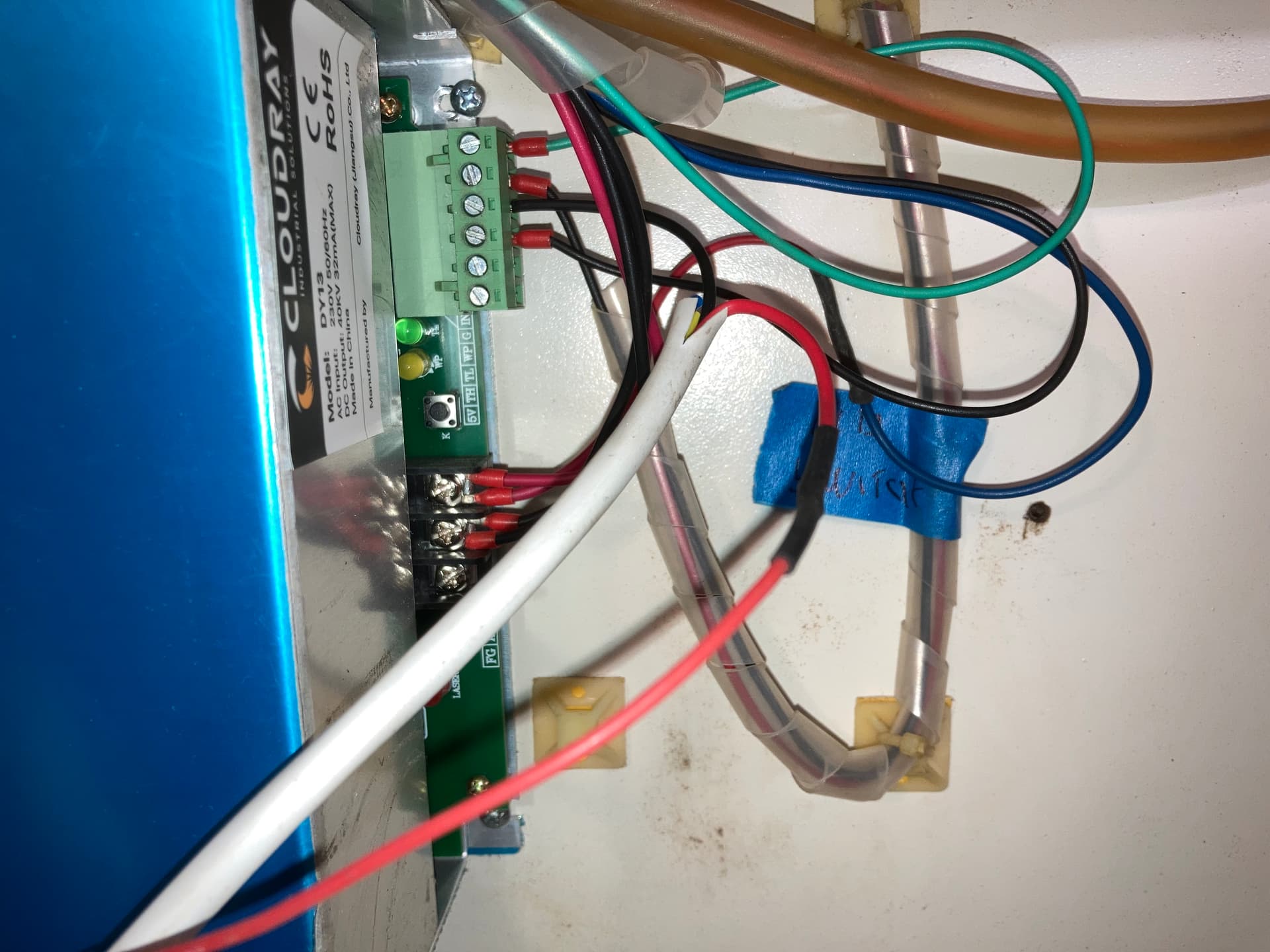
Box on the picture says AC so mains… but as it has a metall housing you use gnd as (yellow/green ) as well
Three wires: the power supply also need a connection to circuit common as the 0 V reference for the two signal connections.
That’s the wire between GND on the controller and G on the power supply.
Just making sure it doesn’t get lost in the shuffle. ![]()
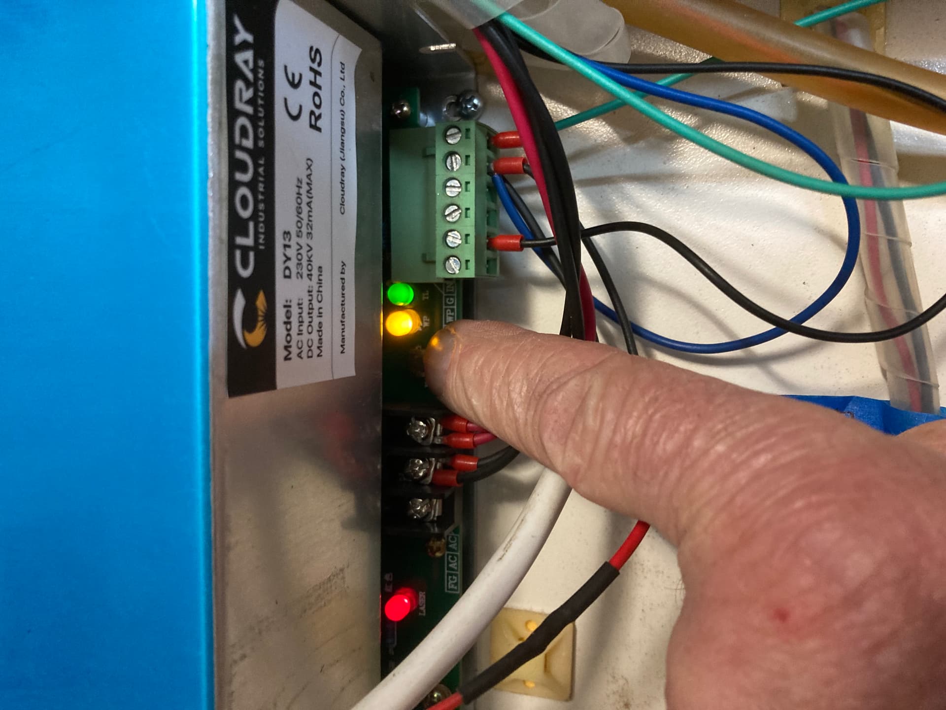
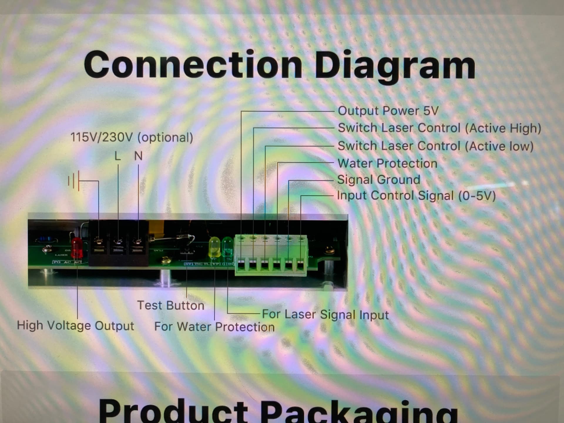
OK, yes good grounds. when I press the test button on the lps with the lid open this is what I get. The laser does not fire though
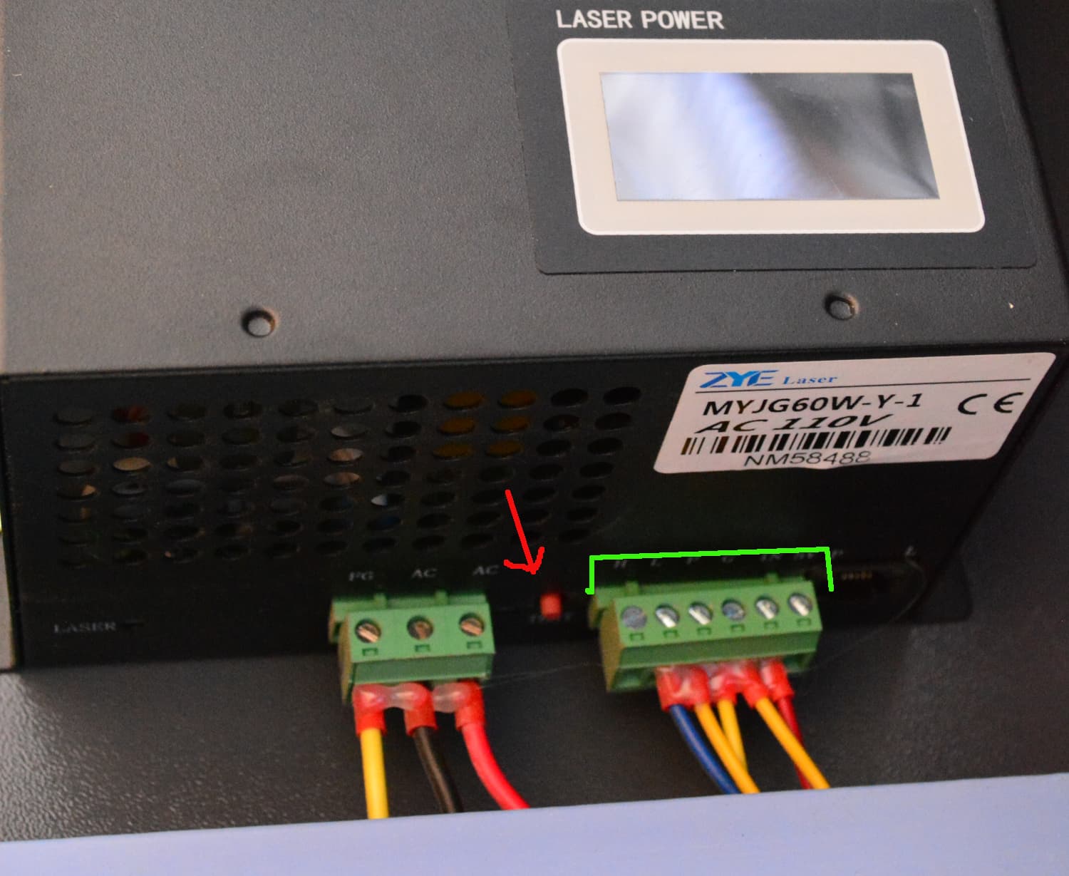
In your photo, P or WP is not wired to ground. In fact there is no wire to the G terminal in your photo. You must have a common ground between these units.
If the water protect is left open, it won’t lase.
Mine is wired to the G terminal, which activates the lasers water protection circuit. If it’s not grounded, it won’t lase.
In order to test it, you have to pull the right hand connector, green (control signals) off the lps, then the test button will operate.
Note that I use L, P, G and IN, you are missing one or two…
![]()
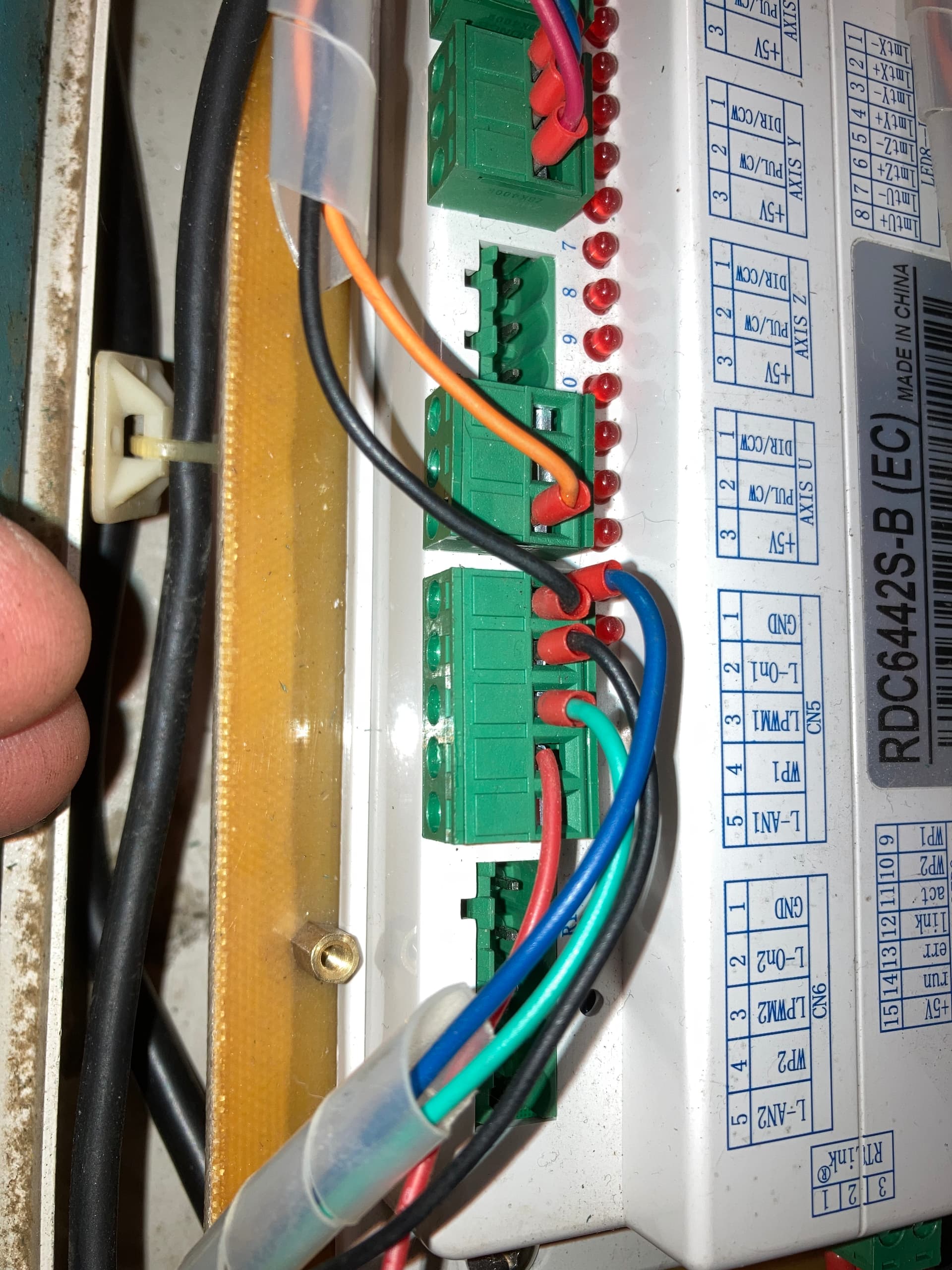
The two exposed screw terminals immediately to the left of your fingertip carry 120 VAC: a layer of electrical tape would be a Good Idea™ before you do more poking around in there.
Source: Been there in other equipment, done that just once, never again. ![]()
You have to poke your skin hard enough to get down to the screws. I’ve reached in there many times and unplugged the signal connector.
Of course, there is voltage there, maybe that’s why I put one hand in my pocket.
![]()
Ed, Jack… you guys are great! I would like to focus on the 2 wires I am confused with. On the Ruida I have the following in CN5
1-Gnd wire to motor control stuff
Ground wire to LPS “G” terminal (blue)
2. L on 1. empty now
3. L pwm 1. empty now
4. WP… wire to water protect switch on chiller (ground going to LPS “G” terminal
5. Lan 1. empty now
on the LPS (cloudray DY13)
5w. empty
TH. empty now
TL. empty now
W. empty I used the one on the Ruida
G. 1 to “Gnd” on Ruida (blue)
1 to door switch (black)
1 to water switch on chiller (black)
IN. empty now
I have 2 wire that I can connect from Ruida to LPS
can you tell me which 2 terminals on each unit I should use and what to what?
Am I correct in the assumption that the controller will pull these to ground in order to be able to fire the laser
You had this wiring correct on some of your photos, why do you keep changing them around…
You’ll will never get this to work unless you stop guessing and re-wiring things.
I laid out where these go in post 16.
![]()
So, just to be sure. Lon1 goes to the AC voltage input on the LPS?
It hasn’t changed from before.
![]()
Am I correct that what you refer to as L is “active low”