I don’t think this has come up before, it has please point me in the right direction
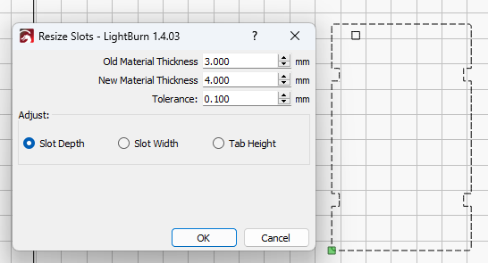
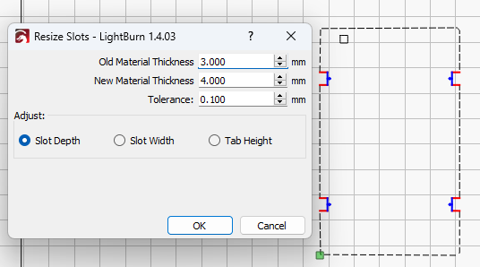
I select all the pattern, go to “Arrange” and select “Break Apart” I then select “Node Editing” and press “ALT J” (to join all nodes) The I proceed to the “Select Tool” then Click on “Tools Tab” then to “Resize Slots in Selection” Change the old size to what it is and this case it’s 2.250mm and on the "New Size to 3.00mm.
Slot width will change the width but not the Height…
Slot Depth and Tab Height do nothing…
This was all starting I think about version 1.4.1 so I installed 1.4 version and rechecked again and it’s the same, so what if any thing am I doing wrong please All was working 6 months ago when I was playing around now I have some Doll Furniture to do and all has to be changed down to 1:12th scale then all slots and Tabs have to be changed to 3mm…Cause I working in 3mm mostly…
Hopefully this all makes sense and the file I upload gets there… Merlin…
Nearly forgot Sculpfun S9, controller, (firmware unsure about such things).
This is a job you’re going to have to do manually I’m afraid.
The Shapes need more slots and tabs per side for it to work.
You need a shape with 2 or more consecutive slots with 3 sides or a minimum of 3 tabs. It will not recognize the outer tabs as tabs either.
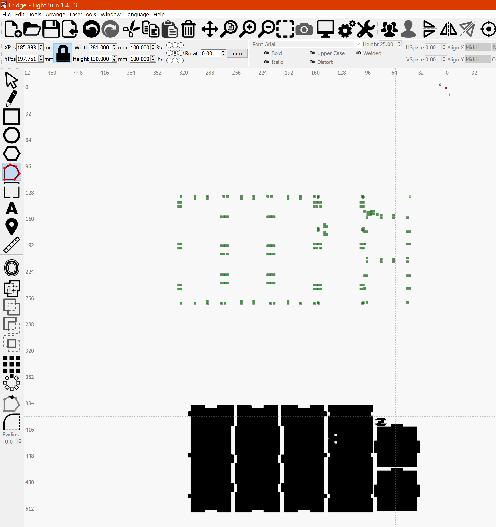
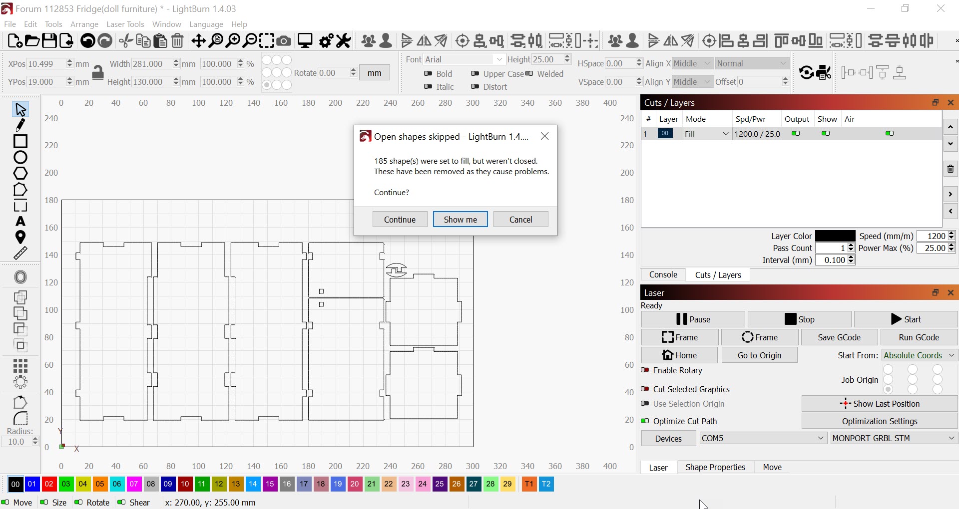
I found a bunch of orphaned nodes in the file you may want to delete before you make your cut. I have attached some screen captures.
Thank you Melvin, I think I understand…Will look at the Slideshow, and get back soon…Health problems Heart playing up, happens when we get a spell of damp weather. Need another quadruple bypass but doc reckons I won’t survive it… Merlin…
Forgot to mention some of these patterns are to large so I reduce them 75% then I have to change all the slots and tabs…
Melvin…All good thanks to you…
It’s looks like the main problem are rogue nodes…
As soon as they are cleared away things started to work…
They are a pain as there are so many but only in this particular set of patterns…
@JohnJohn@LightBurn : I received many reports of this problem. I could solve nearly all of them with the shape optimizer tool. Is there any way that you could integrate these functions somehow? I could imagine a “fix shape” button in that window that silently does the “fit shapes to lines” operation in the background. Or at least put a note in the tab-resizer window, that people should run the optimizer before trying to resize tabs?
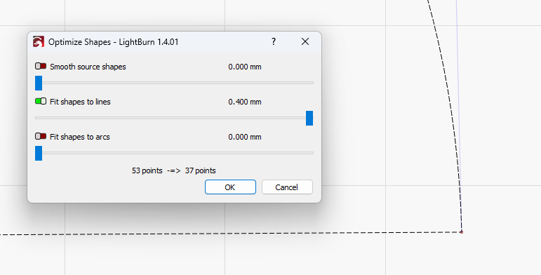
The file from Merlin is a good example. The optimizer doesn’t seem to change anything, the number of points is not changed and I don’t see any difference. But the resizer only works afterward.
I suspect what’s happening is that many of the apparent lines are defined actually as curves. The optimizer is likely converting all of those from curves to straight lines.
Resize slots will only work on straight line segments from what I’ve seen.
I’ll ask the dev team about this. It seems like a great answer for a narrow scope of technical inconsistencies. Please post any feature suggestions to the Fider site linked here in blue.
An option in the LightBurn trace tool removes small closed shapes or glitches from tracing. I don’t believe the Trace tool generates the single nodes seen here as an error.
When folks choose to work with a free pattern, or from a “laser-ready file” offered by an online retailer they’re occasionally at the mercy of how those patterns are constructed.
@nzmerlin I’m interested in knowing how the orphaned nodes arrived in your pattern. Did you draw it, find it online, or import vector art from a source art file?
This makes sense to me. A hover tool-tip message might be considerably easier to implement.
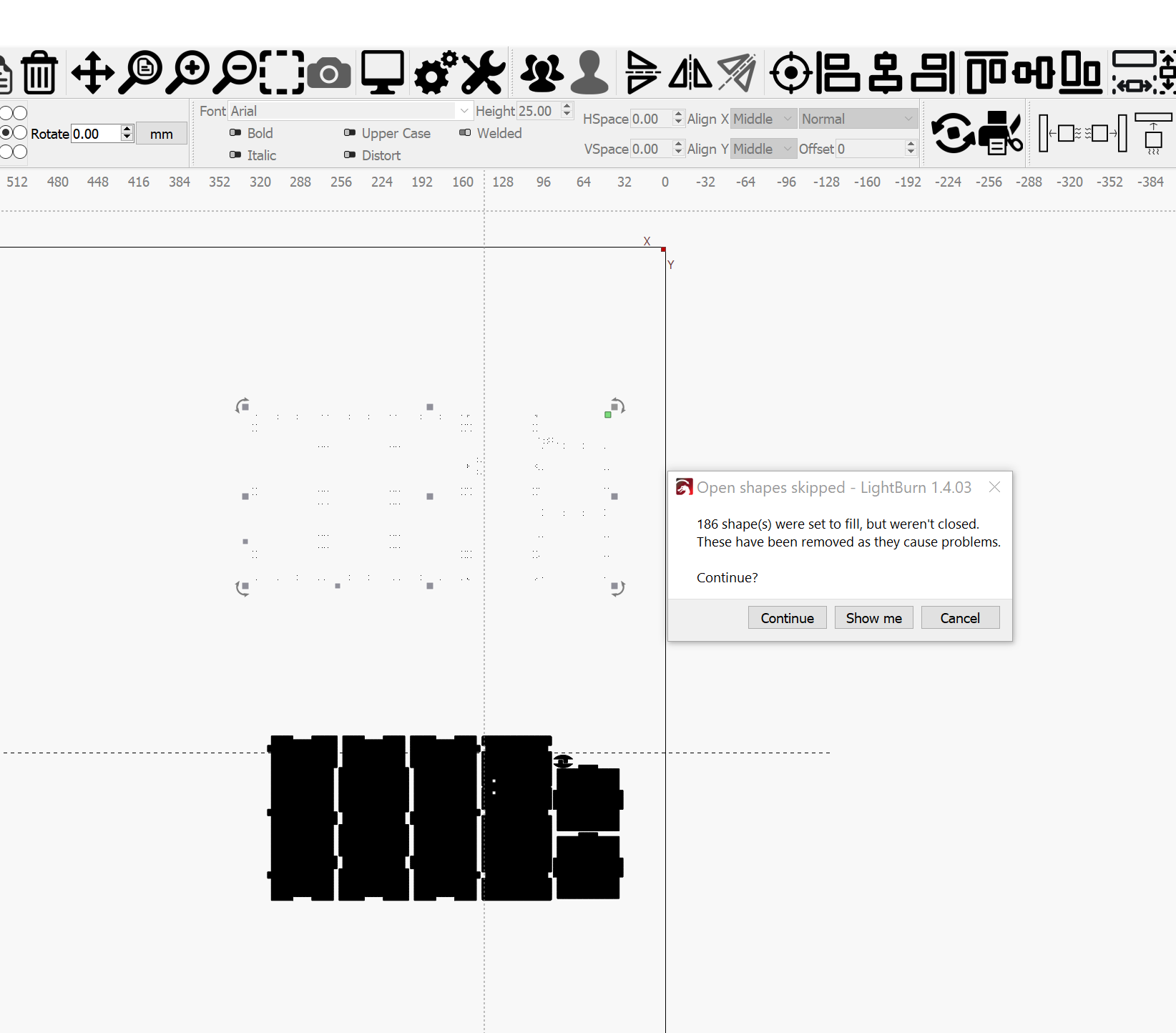
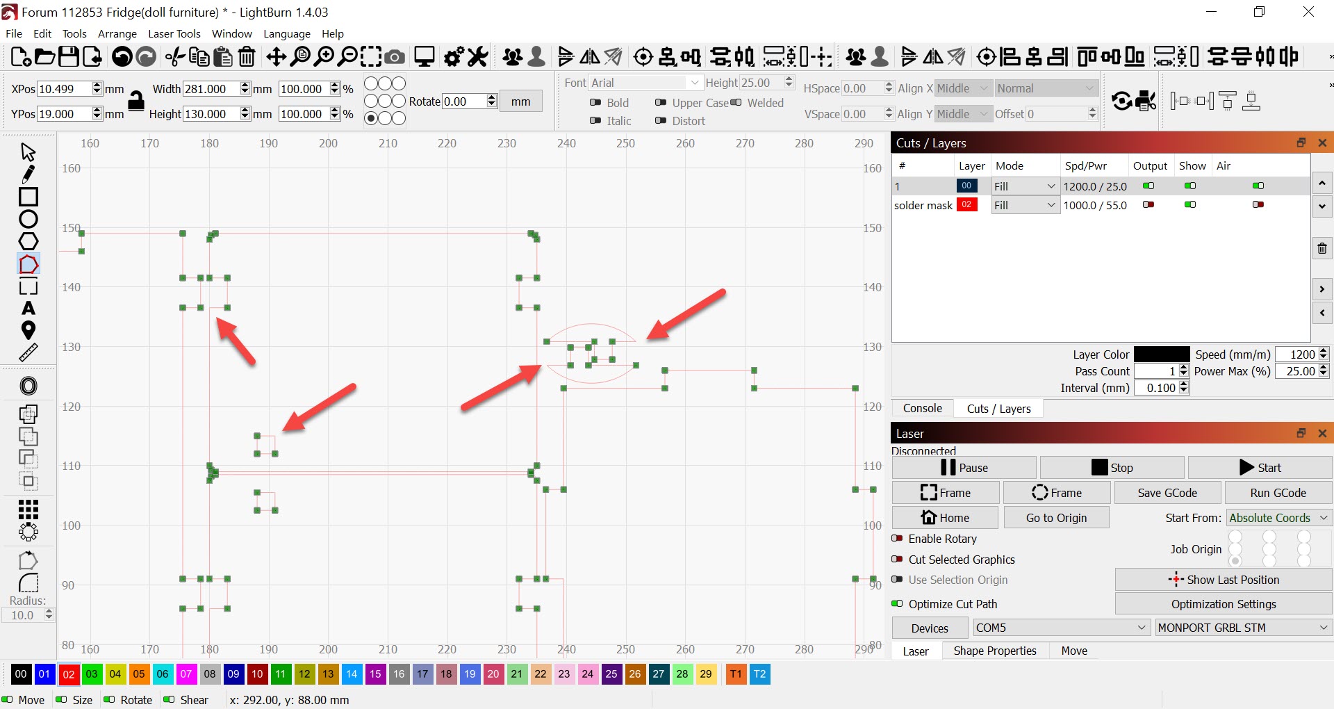
If this pattern was generated by an algorithm it shouldn’t come with the 187 open shapes (orphan nodes) that showed up here. I tested @Rob_H 's elegant approach of setting the problematic layer to filland saw the orphan nodes as well.
This file is actually composed entirely of Bezier curves, whose end points and tangent handles are identical.
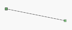
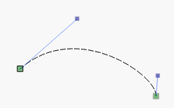
A line is normally defined as two points, like this:
And a cubic Bezier curve uses four - two end points, like the line, and two additional points called “handles” which tell the curve the direction and “speed” to leave each of the end points, like this:
If you take those two handles and move them to be in exactly the same place as the end points each one is attached to, the result is mathematically a straight line, but LightBurn doesn’t check for this - the thing is called a curve, and whatever art package created it called it a curve, so we do too.
The Shape Optimizer will detect these and make them back into lines, but PY is correct - there’s no visual cue this happened, so it’s hard for a user to see it. It’s the first time I’ve seen anything like this, so it’s not common.
I’m genuinely curious how this file was created or where it came from. If it was an SVG, I should be able to make LightBurn detect “perfectly straight” Beziers and just make them lines again.
Yes, I think all of the files that had such problems have been from one of the “free” (I think mostly pirated) vector download sites. Those files are neither generated by LightBurns algorithms nor with one of the online generator tools (like boxes.py). Low-quality files usually.
I have some more files that I downloaded from 3axis and similar sites that show the same effect. I will search and post them here. If I recall correctly, some of them might have been Corel Draw files that I converted to SVG using Inkscape. So this might also be that the Inkscape algorithm uses curves instead of lines.
I converted this file Free Download - 3axis.co via Inkscape (latest stable 1.3) to SVG. I was not able to edit any tabs, no matter whether I used the optimizer or not. Maybe it’s the tab size to shape size ratio that doesn’t fit.
So it might not be related to Inkscape, but to DXF file import? Though, this is a very small amount of samples, I will search for the other files.
In general, LightBurn preserves the data it is given. If you import a file that contains rectangles with extra nodes in them, you might have done it intentionally (for example, nodes along a line could be used as start points for lead-in).
For this reason, I’m reluctant to start making LightBurn arbitrarily alter things that have valid uses.
In the case of Bezier curves that are actually straight lines, I can’t think of any valid use for those, so detecting and replacing them with lines would be fine.
The DXF is entirely modeled with DXF splines (NURBS). There are no straight line shapes in the file at all, just NURBS, and the subdivision routine LightBurn uses to find “corners” isn’t absolutely accurate. I can see if that can be improved, but this might just be a case of the user having to run the optimizer first. We can only hold your hand so much.
Yes, but since (at least to me) it’s not obvious that the optimizer should be run before the resizer, I think it might make sense to put a note into the dialog window letting the user know that he can try to improve the shape to get the resizer working.
That file is entirely cubic Bezier splines, even for the straight lines. I’ve added code to detect this and just import them as lines.
That file also has nearly every point in the shapes doubled up, at least for those weird curve lines, so I now correct & detect that too.
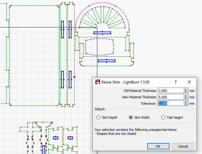
The next major release of LightBurn (1.5) will have some other changes in the slots resizer. Green lines are straight, pink lines are curves, and red circles are breaks in the shape, and we’re drawing node points and tangents too: