@Obicom @Skreelink
Check out the 1.4.02 beta build here: LightBurn-v1.4.02.exe - Google Drive
No guarantees that will work but I believe I made it do what you were suggesting, so hopefully it does.
@Obicom @Skreelink
Check out the 1.4.02 beta build here: LightBurn-v1.4.02.exe - Google Drive
No guarantees that will work but I believe I made it do what you were suggesting, so hopefully it does.
Nope, quickly tossed an image in and while it says B and 360 now, goes to initial start with Y/B, then it outputs X/B for the rest of movement. All movement should be between Y/B.
G21
G90
G0 X0 Y0 F3000
G91
; Image @ 12000 mm/min, 100% power
M107
M05
G0 Y-20.755 B-0.022 F3000
; Layer C00
G1 X5 F12000
M03 P100 S255
G1 X0.08
M05
G1 X0.079
M03 P100 S255
G1 X0.08
M05
EDIT: Looking at the layout, X scanning should be B (assuming 0 degree scan angle) and Y scanning as normal. I can’t do any physical tests right now, because I’m at work, but I can read over the gcode. As such, the way it looks, it’s initial movement G0 Y-20.755 B-0.022 F3000 is reverse. In the preview the head moves X negative (assuming laid flat) so it’s scanning Y as X in that first move, and B as Y. For the project I did, I put the user origin center bottom of the image which is 50mm. So it should have scanned B-20 first, then scan back across B in place of X, then Y bumps up the interval.
Can you try it with just vectors?
I think I just missed the image code path, but for now lets see if vector works.
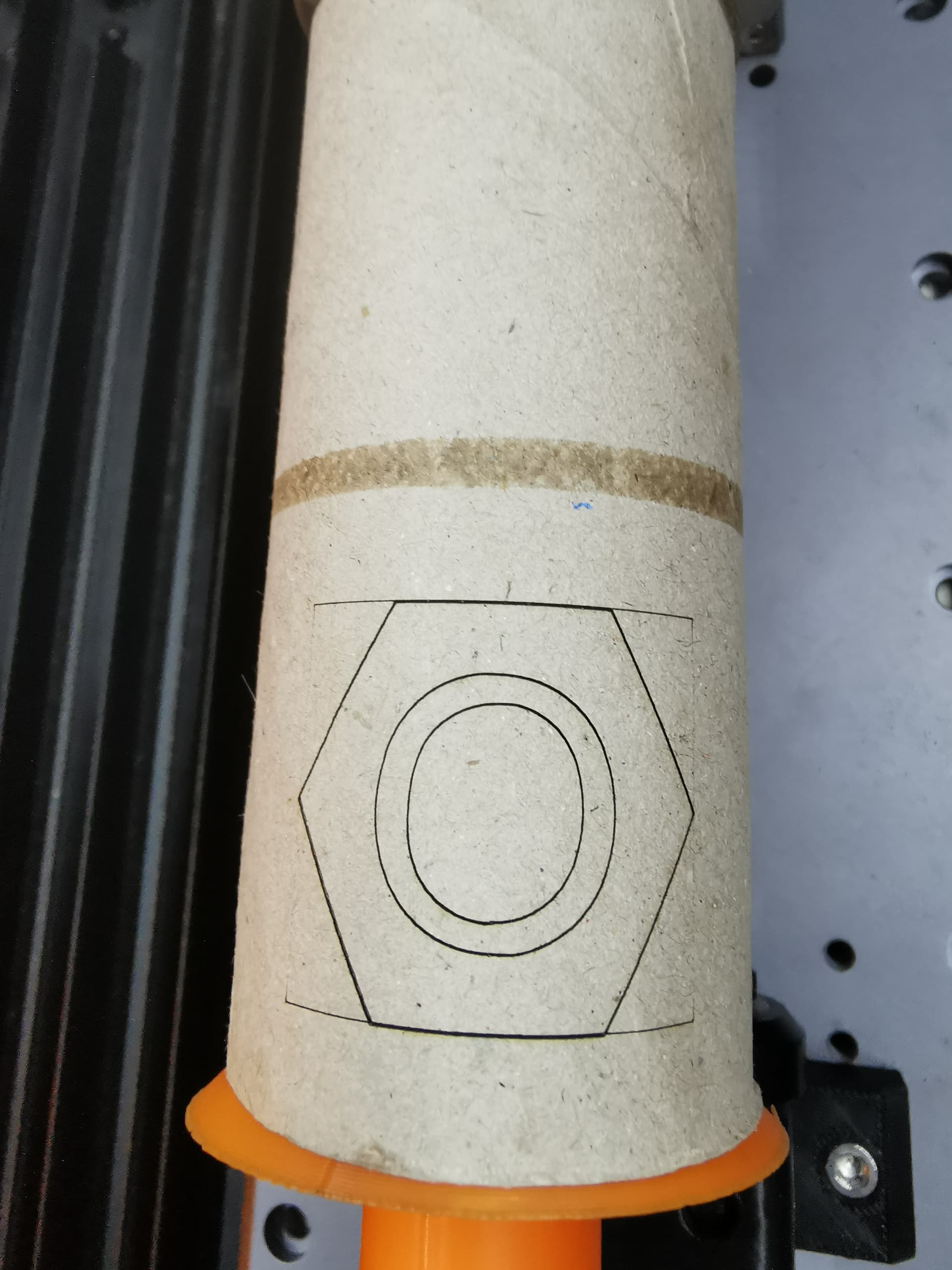
Vector is better, but still seems reversed.
G21
G90
G0 X0 Y0 F3000
G91
; Cut @ 12000 mm/min, 100% power
M107
M05
G0 Y25 B0 F3000
; Layer C00
M03 P100 S255
G1 Y-50 F12000
G1  B69.365
G1 Y50
G1  B-69.365
M107
M05
G90
50x50 square, center bottom origin. Swap Y and B outputs and it should be good.
So Y is actually the rotary?
@adammhaile I installed new beta and did a first try. In Rotary section it looks better but stll B axis. (I would expect A) And if I do a try rotary is not moving but x axis and this is again the no-go. So X xaxis is doing what rotary should do. I do not know how it looks for Y. As I know Lightburn got an Artisan for testing … why you not use it to make Snapmaker (Artisan) compatibel at all with a finished pre-set?
No, B is the rotary, and Y moves the bed. It’s the layout that is the problem. When outputting a rotary project, Y scans along the X axis, and B scans along the Y axis. Basically, you’ll have to layout your project (currently) as if you’re looking at the machine from the side instead of the front.
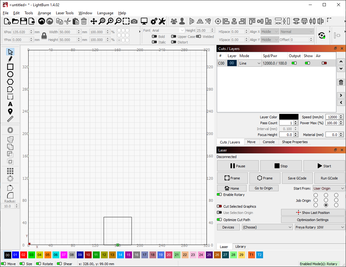
Example; You setup a project like this. Assuming you’re looking directly at the front of the machine since the rotary faces forward and rotates left/right.
In the preview, the laser moves right to start at the bottom right corner first, turns on, and moves clockwise, heading left first. You would assume (given the layout and perspective) that B would turn, since it’s going left/right. However, it’s moving in Y.
G0 Y25 B0 F3000 ; Moves right
; Layer C00
M03 P100 S255 ; Laser on
G1 Y-50 F12000 ; Moves left
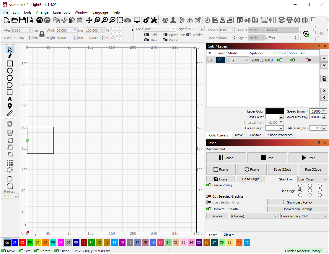
Basically making the entire project rotated 90 degrees. This CAN be used, however, if you set the entire project up rotated like this;
My guess it’s because most all other rotaries (and how Lightburn have it setup) rotate forward/back, whereas the snapmaker rotates left/right. That’s what I meant by Y/B need to be swapped. ![]() Y should move up/down and B should move left/right. Sorry if I sound confusing.
Y should move up/down and B should move left/right. Sorry if I sound confusing.
Exactly - B is the rotary axis and Y is the linear traverse up and down the ‘cylinder’. X axis is not used, apart from manual centering along intended axis.
Thanks for your efforts here, you beat me to it. ![]()
“Manual” centering… ha. ![]() I’m all about that automation.
I’m all about that automation.

@Skreelink this is very helpful. Thank you.
Just curious - can you confirm that the configuration shown in that video is the ONLY way you can use the rotary on that machine? It can’t also be setup with the rotary replacing the Y?
I mostly ask so I know if I have to support both. Otherwise I know how to fix the issue.
One of the support team has the machine but none of the devs and they weren’t around. The company is all remote so no easy access to any possible machine.
Just went out to confirm it. The rotary module physically cannot fit between the gantry turned 90 degrees. The length of the rotary baseplate is listed on their website as 384mm, and a quick check looks to be about 340mm between the gantry. Otherwise, there’s no predetermined holes to mount the rotary unit itself without the baseplate either. The only other way I could see would be to model up a replacement base and position the holes to mount sideways, and 3d print it. However, consideration will have to be made about how much this would limit the capacity of, and the wires coming straight off the back might tangle in the gantry.
Edit: Don’t mind my overthinking rambling. ![]()
Ok, cool. Then no for our purposes. Thanks!
Not a problem. ![]() Hopefully I can help iron out everything.
Hopefully I can help iron out everything.
@Skreelink & @Obicom
Please try this out: LightBurn-v1.4.02.exe-snapmaker.zip - Google Drive
Per your descriptions, this should work. Please be sure to also try out vector, images, and framing functions.
Please note: since this is a one-off build it’s not signed and Windows will complain. I promise it’s ok ![]()
While I can’t do an actual test since I’m at work, looking at the gcode it spits out, and loading into Luban for a preview, it’s looking good. Though, the preview in Luban is stretched, likely because it doesn’t know the diameter of the stock put in Lightburn.
Yeah, it would be stretched because it’s converting from mm to degrees.
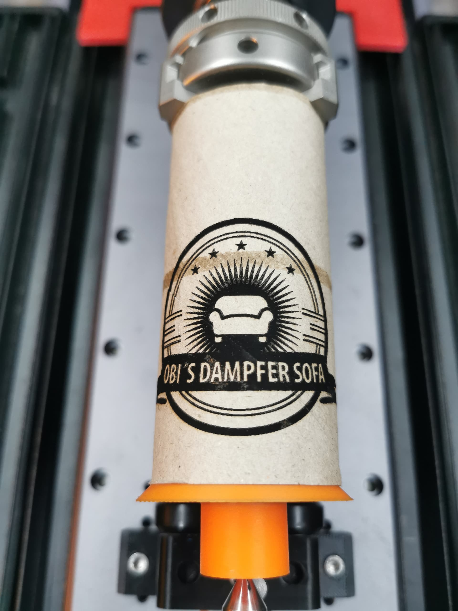
@adammhaile Hello Adam, I am currently doing my first try in image mode with the new beta version and first time it looks good (still work in progres) One additional think I find strengh but has nothing to do with the rotary module. If I start a job “from current possition” it lifts the laser 9mm up … I guess is part of the gcode. Do you know why and maby how I can change that? I don’t wont to lift the Z axis with the start. Normaly I adjust the laser head directly with the focus high of 10mm and want to start exactly from this position without a lift up. Do you understand what I mean?
@adammhaile Hello Adam, now I can confirm that fill mode, line mode and frame mode working correctly. Now it is time for me to get more familiar with Lightburn ![]() Maybe you have an answer for my last question, why Lightburn lifts up my Z position to 9mm with starting a job from “current position”. It is not a big deal but would nice to be able to avoid this behavior. Best regards, Dirk
Maybe you have an answer for my last question, why Lightburn lifts up my Z position to 9mm with starting a job from “current position”. It is not a big deal but would nice to be able to avoid this behavior. Best regards, Dirk
One addition that I could observe … with the end of the job the laser is still switch on. I would expect that the laser would automaticly switched off after the job. This could be a security related topic on the end.
can you send me the code for that job? That should definitely not happen