“There shouldn’t be reason not to,” … to unplug/replug the Y-Axis and Rotary cables with the power on, as long as the drivers don’t have the Enable pin active, right?
you should never disconnect a motor while the board is powered. doesn’t matter if the enable is on or off
If it’s not enabled, the motor shouldn’t be powered. The driver is, but not the motor.
I always think about this every time I never power the laser down and just use my three position selector switch. Still haven’t bricked anything.
Illustrated here:
Yeah, I actually saw that. Ideally, I think I’d like a different driver for the rotary, but for a shared driver, I think that using the enable input is safe.
You know, it’s not like any of these components are that expensive. I’ll risk it. I switch it all the time. I think it is a non issue.
Alternatively, yes you could switch at the controller output to a different stepper driver. But then you’d be hot swapping a motor on to that live driver. So essentially the same risk maybe.
And, unless you have a shelf full of spare parts, you are out of action until you get the replacement. ![]()
I think the “best” (depending on your definition…) would be two drivers, and a DPDT switch/VLSI. The Y-AXIS gets its own driver, and is one side of the DPDT for DIR/PUL. The rotary gets it’s own driver as well and is the other side of the DPDT. Only one enable pin active at any time. With either axis primary; disable the driver, flip the DPDT, enable the other driver. The sequence controlled by some digital logic so all you have to do is have a physical switch in the “A” or “B” position (or Lightburn control) and the switching happens safely and automatically. If you really want to be safe, put a lockout on the rotary connector so you can’t enable unless it’s connected.
Or, accept your own level of risk do what’s best for you. ![]()
My X-Axis limit switch failed yesterday and my rotary doesn’t get here until next week, so I added the stepper disable switch:
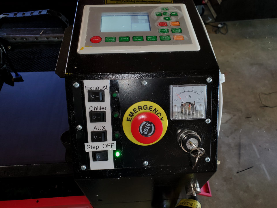
Of note:
- Just like the rest of the outputs so far, Ruida has the positive side common and the ground/negative being the enable.
- I extended the DIR+/PUL+ 5V to the EN+ on each driver.
- I used GND from the unused Ruida CN6 because the power supply ground isn’t common.
- You might think I was using the green “Step. OFF” indicator because it’s safe to move the Y-Axis cable. It’s actually because I’m lazy. I used one side the DPST switch to light up the existing LED, and the other side just completes ground to the stepper Enable (disabling the steppers). Otherwise, I’d have to replace the current limiting resistor, bring +5V up there, etc. etc.
I verified that the stepper windings are at 0V when the driver enable is not active and that both axis are free to move by hand. 0V = no back/counter-EMF, so nothing to damage the driver MOSFETS. “It’s safe enough for me.”
Replacing the limit switch was a pain… Simple, but trying to route the wires through some of the hidden sections of the chassis was annoying.
Received the rotary and have been playing with it a bit. To make it easier for me, I have a set of normal vs rotary Ruida settings saved; modifying acceleration, primarily. All I have to do is remember to load the right profile. 
Being able to disable the steppers without losing the rest of the current state of the controller is convenient as well. Disable steppers, manually move X/A axis where I want them, re-enable and save the origin.