Totem S with Limit Switches / Homing

Your firmware must assume that upper right is origin although you have it homing to lower left.

Try this:

$10=0 ; this changes your controller to report work coordinates instead of machine coordinates
G10 L2 P1 X-299 Y-299 ; sets a work offset to get you 0,0 for lower left

Is your actual working area 300,300? You may have an ease-off set that’s making it go to -299, -299 instead of -300,-300. You can adjust the specific values depending on how you want this to work.
There is an “ease-off”, so that explains the -299 as opposed to -300.

After executing “G10 L2 P1 X-299 Y-299”, it now reports “X=0 Y=0” after homing.

I experienced another issue yesterday that I need to trace further. I ran a simple project with two layers. The first was an engrave, the second a cut. When it finished the “engrave” layer, the head moved up to the right several centimeters and then back down before starting the “cut” layer. This worked ok because the object was really small. I then enlarged the object, and this time the head max’d out the travel to the upper right before the “cut” layer, causing the steppers to grind a bit. I’m not understanding why the head would move away from the object between layers. I just started using LightBurn yesterday, so I understand that I have a LOT to learn.

Thanks again for your assistance…

Since your coordinates were not correctly zeroed out yesterday I’m assuming you were working with Start from in the Laser window set to “current position”. If so, LightBurn won’t necessarily know where the laser is positioned on the machine and will be happy to send instructions that potentially crash the head.

I suggest you switch to Absolute Coords until you get very comfortable with how LightBurn and your laser work. Absolute Coords is very simple because your workspace in LightBurn matches 1:1 with your work area. So what you position in the upper left in LightBurn will correlate to the same position on your laser.

This will prevent most crash scenarios.

You may also want to configure soft-limits to be on ($20=1). This will prevent certain additional crash scenarios.

Regardless of the positioning method, why would the head move far away from the object between layers? The laser work area is 300mm x 300mm, and it started down in the lower left quadrant. The object (both layers) is only 30mm x 40mm, so if it started in the lower left corner for the first layer, I would expect it to return to that point when starting the second layer.

Likely something in the design. Upload here and I can take a look.

See my commentary on AtomStack here, this sounds similar:

I believe that the issue was related to the setup prior to having the limit switches installed. LightBurn was set to “Current Position” instead of “Absolute Coords”. Now that I have everything setup, it worked properly.

Also, when I executed “G28”, the head moved to the back-right corner and ground the steppers. I’m assuming this is because the homing was handled by the controller board and not positioned by LightBurn.

I’ll hold off flashing a new firmware until I can be assured I won’t brick he unit!

When I click the “Home” icon in LightBurn. what command(s) are being sent to the printer? I ask because when I click the icon, it performs the expected homing sequence using the limit switches.

I’m not familiar with G28 but I suspect it’s going to machine 0,0 which we know is back right.

I believe it uses $H to initiate homing. You can see all chatter between LB and the controller if you enable “Show All” in Console.

I believe that I need to move the limit switches to the back right instead of the front left. I initially went with front left because of a video I watched and that’s how it was done, plus, my 3D printers both home to the lower left and that’s what I’m used go.

What leads you to this conclusion? It should be arbitrary how this is done.

When I send the commands to the laser to set using the homing switches in the lower/left, it head homes to the lower/left, but when I start a print, the head shoots to the back/right and grinds the steppers. It appears to be sending a different “home” command at the start of the job. I’m still learning about the gcodes as well as what the laser interprets.

Oh. Thought we were past that.

Can you do the following please:

  1. Send a screenshot of your Device Settings screen.
  2. Send output of $# in console
  3. After homing, move the laser to each corner of the machine and run ? in console. Respond with which corner and the output of the command for each please.

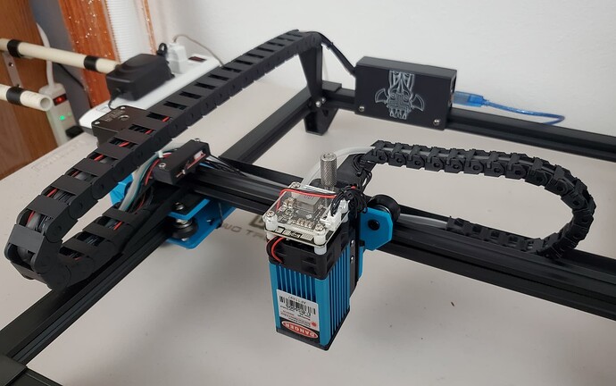
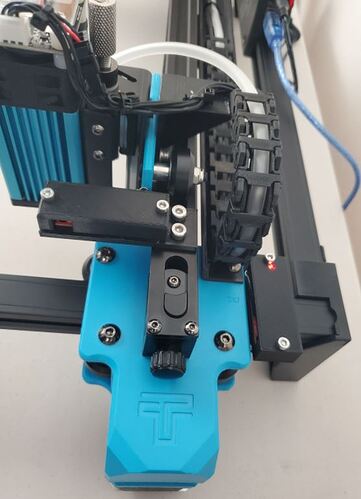
I’ll do that after work today. I spent the weekend adding wire chains to the setup.

I have a couple of 3D printers, so I was able to design and “print” custom mounts for each end of the chains.

Started by homing the laser head.

$#
[G54:0.000,0.000,0.000]
[G55:0.000,0.000,0.000]
[G56:0.000,0.000,0.000]
[G57:0.000,0.000,0.000]
[G58:0.000,0.000,0.000]
[G59:0.000,0.000,0.000]
[G28:0.000,0.000,0.000]
[G30:0.000,0.000,0.000]
[G92:0.000,0.000,0.000]
[TLO:0.000]
[PRB:0.000,0.000,0.000:0]
ok

Back right (position after homing)
?
<Idle|MPos:-1.000,-1.000,0.000|FS:0,0|WCO:0.000,0.000,0.000>

Back left:
?
<Idle|MPos:-300.000,-1.000,0.000|FS:0,0|WCO:0.000,0.000,0.000>

Front left:
?
<Idle|MPos:-300.000,-287.000,0.000|FS:0,0|WCO:0.000,0.000,0.000>

Front Right:
?
<Idle|MPos:-1.588,-287.000,0.000|FS:0,0|Pn:X|WCO:0.000,0.000,0.000>

The switches are now in the back right corner. I actually like it homing back there because it gets the head totally out of the way.

I haven’t attempted printing anything yet. What will be the effect of the negative coordinate values?

What position is the origin in Device Settings now?