Understanding line interval/DPI for engraving

First, I’m no expert so anyone else here feel free to correct any misstatements or add your own information.

I’m specifically addressing this question for engraving, whether it be photo engraving or filling an enclosed vector shape. The reason for this post is it seems like a lot of people either don’t understand it at all or they take a guess at it and see what looks good. This is specifically tailored for CO2 lasers as I don’t have any experience with diodes.

If your laser head is stationary and properly focused, when you fire a pulse what you get on the material is a circular dot. The size of the dot you get will depend on the lens, the power setting, the amount of time the laser is fired, and the material it’s being fired into. We’ll come back to this dot.

To make this discussion easier to understand I’m going to grossly exaggerate some numbers and stick with imperial measurements. For the sake of this discussion let’s assume we’ve drawn a square that is 8" x 8" and we’ve asked lightburn to fill this square. You know that LB will start at the upper left of the square, fire the laser, move across to the right in the x axis, move down a bit in the y axis, then fire back across to the left side of the square, move down a bit, etc. until it gets to the bottom of the square and the job is completed.

Now, let’s assume that the dot we talked about earlier is a whopping 1" diameter dot. If that were the case the job would start, fire the laser, and move to the right side of the square. We would have a 1" tall burn line across the top of our 8" square. Now it’s time to go back to the left. But the laser head needs to move down some in the y axis first. How much? Depending on what your objective is, most people would want it to move down 1" then start burning back to the left so that this second line is burned right underneath the first line with no gap and no overlap. In this example we’d want a line interval of 1" and a DPI (dots per inch) of 1".

Let’s now take our theoretical dot size and say that it’s 1/2". In this case after we burn the first line we’d want the laser head to move down 1/2" and then burn the next line. So our line interval would be .5" and our DPI would be 2. This is why the two settings are tied to each other in LB. Line interval and DPI are just two ways of expressing the same thing. One setting is just the inverse of the other.

So you happily have your 1/2" dot burning a 1/2" line, the y axis moving down 1/2", and the next line being burned with no gap and no overlap. But hey? I think I can get better quality if I bump up that DPI number! So let’s set it to 4! We’re going to double the resolution! A DPI of 4 is also a line interval of .25". Now we burn that first 1/2" tall line across, move down .25" and burn the next line.

What happened? Well, you burned that first 1/2" thick line, you moved down 1/4" and burned the next 1/2" line. You just burned your next 1/2" line with 1/4" of it over burning/overlapping the first line.

Probably not what you intended. The point is, if you want your engraving to go line by line with no gaps and no overburn, the setting for the DPI/Line interval is a specific number that can only be derived by knowing what size dot your laser is laying down.

If I know my dot size is 1/2" then my DPI is 2 and my line interval is 1/2". BUT, LB specifies the line interval in mm, not inches. It’s just the common way of expressing line interval. Go set your DPI to 2 and you’ll see your line interval changes to 12.7mm (the equivalent of 1/2").

Correct me if I’m wrong but I believe LB defaults to a DPI of 254. That makes the line interval .1mm. I’m going to guess that if you go measure the size of the dot that your laser is putting down it’s likely bigger than .1mm. I believe that a 2" lens is theoretically capable of a .1mm dot size but is more commonly going to be around .2mm. If your dots are .2mm then your DPI should be set at 127 (if you want no gaps and no over burning).

If you are currently at a setting where there are no gaps and no overburn and you push the DPI up (bring the line interval down) all you are doing is causing your scan lines to overlap resulting in over burning your previous scan line.

There are many factors that contribute to the dot size as I mentioned before. All else being left the same, simply changing the material can change the dot size. Another issue is whether your dots are actually dots. Running the speed in excess of the power supply capability can also be an issue and is a subject for another discussion.

9 Likes

In no way trying to steal your thunder here, but I have been preparing this post for a few days now, and it contains visuals showing the dot size and overlap you discuss, so I just made it public and I’m linking it below:

9 Likes

Russ IS THE MAN when it comes to this subject. Here is a great video describing this concept and how to control that little dot laser burn which creates your image.

Russ and engraving information to make you burn images like a BOSS !

Cheers

Sasquatch

4 Likes

@LightBurn even better! By all means, steal away. Just want folks to understand it. And @Sasquatch, agreed. Everything I’ve learned has been from Russ’ videos. While I very much appreciate all the testing and experimentation he does to arrive at his conclusions, I wish he had some digest videos that simply explained his findings without necessarily including all of the process. It requires a lot of time investment to watch everything he’s created. An educational series from him is something I’d gladly pay for. One thing he stresses throughout his videos is that your mileage may vary. What he’s giving you are the tools to do your own testing and find a formula that works for your machine, not hard and fast settings

@LightBurn doesn’t seem like I can reply to your FAQ so I’ll include this here…

If you want to know what your dot size is, get a loupe with a graduated scale or a calibration slide such as this…

You can run your very own test as well. Attached is a calibration image I made (copied from Russ) where the bottom line is a series of on/off pixels. Each pixel is .1mm. If you run this test your dither option in LB must be set to passthrough!

Dot Pattern

Here’s a picture of that test on a piece of painted ceramic tile…

1322835978591

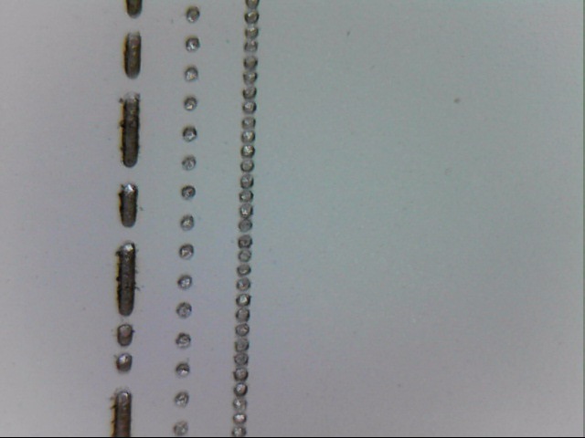
You can see the right/bottom line is the row of on/off .1mm pixels. They aren’t QUITE touching which means each dot is slightly smaller than .2mm in diameter. If those dots were just touching the dots would be .2mm. If there was a dot, a space that would fit another dot but empty, then another dot, etc. then the dots would be right at .1mm.

Here’s the same test on a piece of watercolor card stock…

1322849604251

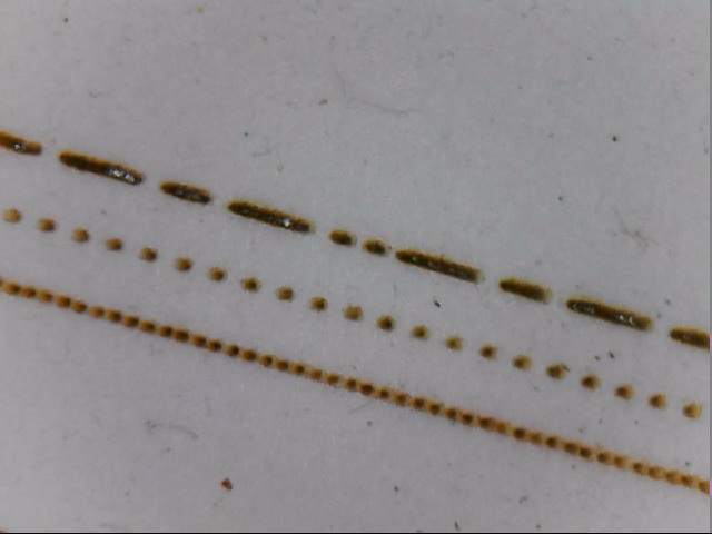
While there is some scorched halo around the dots you can see the dots are much closer to .1mm. You can just about fit another dot between some of them. At the beginning the dots appear to be a little closer together than the middle or end of the line. Most likely because the paper isn’t absolutely flat and the depth of field is just that narrow on this lens setup.

These are both done with the same lens setup. The difference in the dot size is the material and maybe a very slight difference in focus. If I were engraving a picture on both of these materials I’d need to set a different DPI for the card vs the tile even though I’m using the same picture and the same lens.

Would this be a good topic to add in some discussion about “scan line angle”?

I think it would also be nice to have someone list each of the “image mode settings” (e.g. Jarvis, Dither, Newsprint, Grayscale") and suggest in which scenarios each of these might be best.

Has anyone already done a test we could see of using the same image, but then trying each of the image mode settings for comparison?

1 Like

In my understanding of a well-functioning, technically oriented forum, it is generally good practice to add the relevant data to examples that biliver made public otherwise they are not really useful. In most cases, this practice is also complied with here in the forum. A bigger problem is, in my opinion, that the search function is not used enough before new posts are posted, even though there are fine filter options.

I started playing with engraving the other night. Agreed with Russ’ series. It helped me get my first engravings looking pretty good. I am a little confused on his method to figure out the ms delay in firing the beam. I recently replaced my 50w PSU (old one died) with a Vevor one. It states that it had a <1ms response time. I’m not quite sure how to verify that. Also, I got a bit lost in the math to figure out the resolution and max speed I can run the head. The below engraving was done at 67mm/s at 15.5 power. Overall, I’m pretty happy with it, other than the slow speed. If someone has a link or a quick way to explain the PSU delay and how to calculate the speed, I’d be super appreciative as I got lost on Russ’s description. I do have his files and a microscope with a .1mm reticle.

Final print approx 3.5 inches wide on 1/8" Rowmark maple ply.
Image printed at 254dpi (.1 line increment) with Stucki 67mm/s 15.5max 11 min power