First, I’m no expert so anyone else here feel free to correct any misstatements or add your own information.
I’m specifically addressing this question for engraving, whether it be photo engraving or filling an enclosed vector shape. The reason for this post is it seems like a lot of people either don’t understand it at all or they take a guess at it and see what looks good. This is specifically tailored for CO2 lasers as I don’t have any experience with diodes.
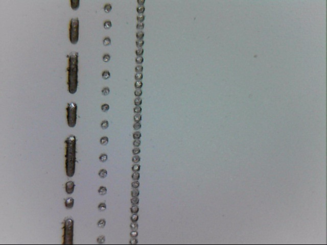
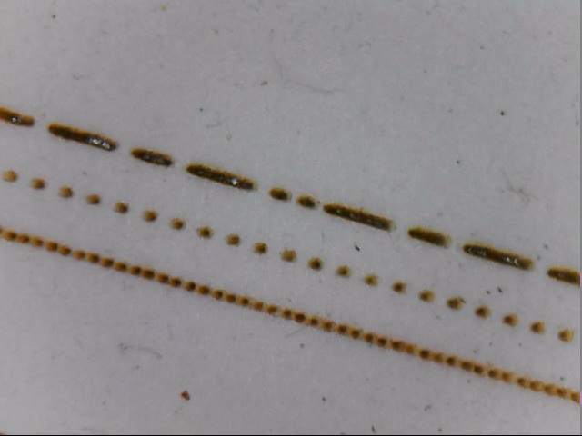
If your laser head is stationary and properly focused, when you fire a pulse what you get on the material is a circular dot. The size of the dot you get will depend on the lens, the power setting, the amount of time the laser is fired, and the material it’s being fired into. We’ll come back to this dot.
To make this discussion easier to understand I’m going to grossly exaggerate some numbers and stick with imperial measurements. For the sake of this discussion let’s assume we’ve drawn a square that is 8" x 8" and we’ve asked lightburn to fill this square. You know that LB will start at the upper left of the square, fire the laser, move across to the right in the x axis, move down a bit in the y axis, then fire back across to the left side of the square, move down a bit, etc. until it gets to the bottom of the square and the job is completed.
Now, let’s assume that the dot we talked about earlier is a whopping 1" diameter dot. If that were the case the job would start, fire the laser, and move to the right side of the square. We would have a 1" tall burn line across the top of our 8" square. Now it’s time to go back to the left. But the laser head needs to move down some in the y axis first. How much? Depending on what your objective is, most people would want it to move down 1" then start burning back to the left so that this second line is burned right underneath the first line with no gap and no overlap. In this example we’d want a line interval of 1" and a DPI (dots per inch) of 1".
Let’s now take our theoretical dot size and say that it’s 1/2". In this case after we burn the first line we’d want the laser head to move down 1/2" and then burn the next line. So our line interval would be .5" and our DPI would be 2. This is why the two settings are tied to each other in LB. Line interval and DPI are just two ways of expressing the same thing. One setting is just the inverse of the other.
So you happily have your 1/2" dot burning a 1/2" line, the y axis moving down 1/2", and the next line being burned with no gap and no overlap. But hey? I think I can get better quality if I bump up that DPI number! So let’s set it to 4! We’re going to double the resolution! A DPI of 4 is also a line interval of .25". Now we burn that first 1/2" tall line across, move down .25" and burn the next line.
What happened? Well, you burned that first 1/2" thick line, you moved down 1/4" and burned the next 1/2" line. You just burned your next 1/2" line with 1/4" of it over burning/overlapping the first line.
Probably not what you intended. The point is, if you want your engraving to go line by line with no gaps and no overburn, the setting for the DPI/Line interval is a specific number that can only be derived by knowing what size dot your laser is laying down.
If I know my dot size is 1/2" then my DPI is 2 and my line interval is 1/2". BUT, LB specifies the line interval in mm, not inches. It’s just the common way of expressing line interval. Go set your DPI to 2 and you’ll see your line interval changes to 12.7mm (the equivalent of 1/2").
Correct me if I’m wrong but I believe LB defaults to a DPI of 254. That makes the line interval .1mm. I’m going to guess that if you go measure the size of the dot that your laser is putting down it’s likely bigger than .1mm. I believe that a 2" lens is theoretically capable of a .1mm dot size but is more commonly going to be around .2mm. If your dots are .2mm then your DPI should be set at 127 (if you want no gaps and no over burning).
If you are currently at a setting where there are no gaps and no overburn and you push the DPI up (bring the line interval down) all you are doing is causing your scan lines to overlap resulting in over burning your previous scan line.
There are many factors that contribute to the dot size as I mentioned before. All else being left the same, simply changing the material can change the dot size. Another issue is whether your dots are actually dots. Running the speed in excess of the power supply capability can also be an issue and is a subject for another discussion.


