Oh, it was marked private. Fixed.

Oh, it was marked private. Fixed.
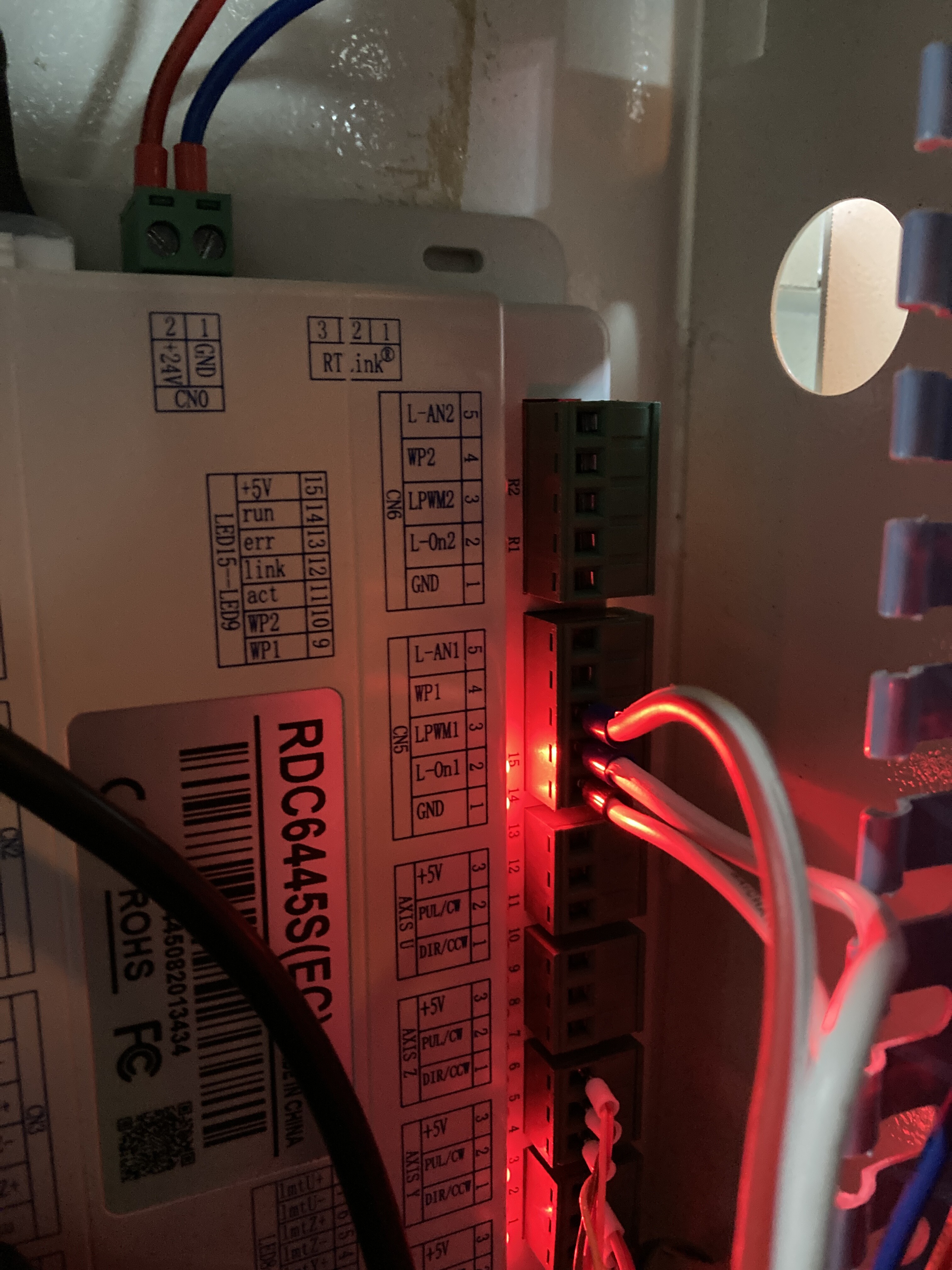
The Ruida is homing at a relatively low speed. It appears to home properly.
It looks like the Ruida is returning to some set position… Here is a short video of my machine homing, then it returns to whatever position it has in it’s configuration.
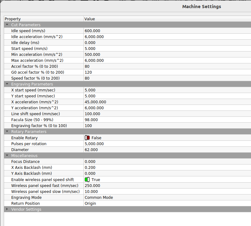
The machine settings have a return position that determines what the machine does after a boot or a successful job run… The options are Origin (user), absolute 0, 0 or no return… At this point, I’d set it to no return. Right above vendor settings…
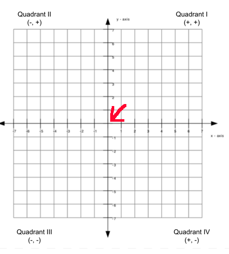
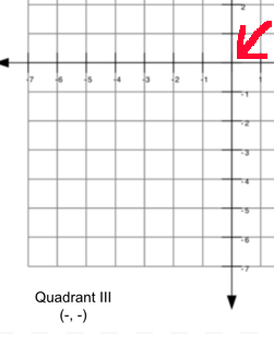
I suspect what you have going on is a quadrant issue…
This is the coordinate system… The red arrow is 0, 0 and is the home location…
If your machine homes to the rear/right, like yours, it’s expected operation region is in quadrant III…
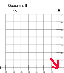
If your machine homes front right, it’s in quadrant II.
It appears to me that the machine is homing, then moving to the user origin… check the return position setting.
If it’s doing that, I believe that the controller is expecting a different quadrant I.E. it’s homing to the rear/right, but it thinks it’s operating in different quadrant, so a move down might go up …
Does this make sense?
Good luck
![]()
No matter what controller my method of setting up a new machine goes like this:
Thanks so much. I’ll take a look at it this weekend and see how to adjust the quadrant after I set it to NO RETURN for the return position setting. Hopefully changing the quadrant is easy to do. Just need to find where this setting is. This sounds like it may be it. For now I’ll just set it to no return.
It is currently moving in the correct directions as per the arrow keys. But they weren’t originally. I ‘fixed’ it by reversing polarity on two of the motor wires. Thereafter the directions were correct.
Thanks Doug. Appreciate the concise troubleshooting steps. I may be back for additional detail on some of those.
Thanks guys!
I’d suggest you get it to home properly first, and then worry about anything else that isn’t correct…
Sounds like you’re gaining on it…
![]()
Okay. I finally had time to get back to this today.
Setting the no return option did fix the crashing of the laser head immediately after homing.
But I’m stuck on how to change the quadrant to quadrant III. Any tips?
Thanks so much for all your help. It’s invaluable.
It seems I’m not the only one who has experienced this exact issue before. Explained so well here:
I am reading the setup guide link shared there now in hopes it will make sense and I can figure it out.
Still taking all input anyone may have. Thank you.
Update:
Well, it still doesn’t work.
If I press the up arrow the machine with crash but it seems this allows the belt to slip a bit and that frees up some slack to move south thereafter a bit. Same thing when I try to go right. It will crash but then I can go left a little bit thereafter.
So I am still in the wrong quadrant, correct?
IF so, I still have no idea how to change the quadrant. How do I easily change the quadrant so the machine knows that top right is 0,0 and that the usable work area is all down and to the left? 400x600mm? Thanks.
The home location of the machine (rear/right) determines the quadrant, you don’t get to choose.
All machine home at 0, 0
You are operating in Quadrant III, rear right.
![]()
Thanks. I appreciate all the help. But then that means my machine is broken and will never work as I can’t get it to function. Where do I go from here?
What is the issue now?
![]()
Hi Jack,
Same issue. Hasn’t changed.
I’m still stuck in that the machine will home then is not able to move around the work area even after I switch the homing position to right rear or left front.
Second issue still remaining after that one is that the motors are erratic. E.g. they seem to still have incorrect accelleration settings or something as they seem to spin out/not catch when I press the arrow keys on the keypad. They also don’t seem to go a set 10mm distance with each press but a much larger and random distance. So dialing in the speed settings seems to be the second thing I need to fix next after the first work area issue above.
Is there someone that I could pay to set up a facetime troubleshooting session with me?
My daughter and son-in-law are looking at me daily to get this thing working finally as we have requested business projects that need to get done by April 15th.
Thanks for anyone able to work with me or if you can direct me to someone.
Well, I got the motors working finally. Spent 9+ hours today (all day Saturday basically) to work it out via brute force trial and error from the control panel. Just reset the default parameters and then kept changing things and noticing the result. Then guessing from there what might work next.
I’m able to home and use the jog buttons in correct directions now.
Also able to use lightburn to move the head around with shapes I’ve drawn.
Next two hurdles:
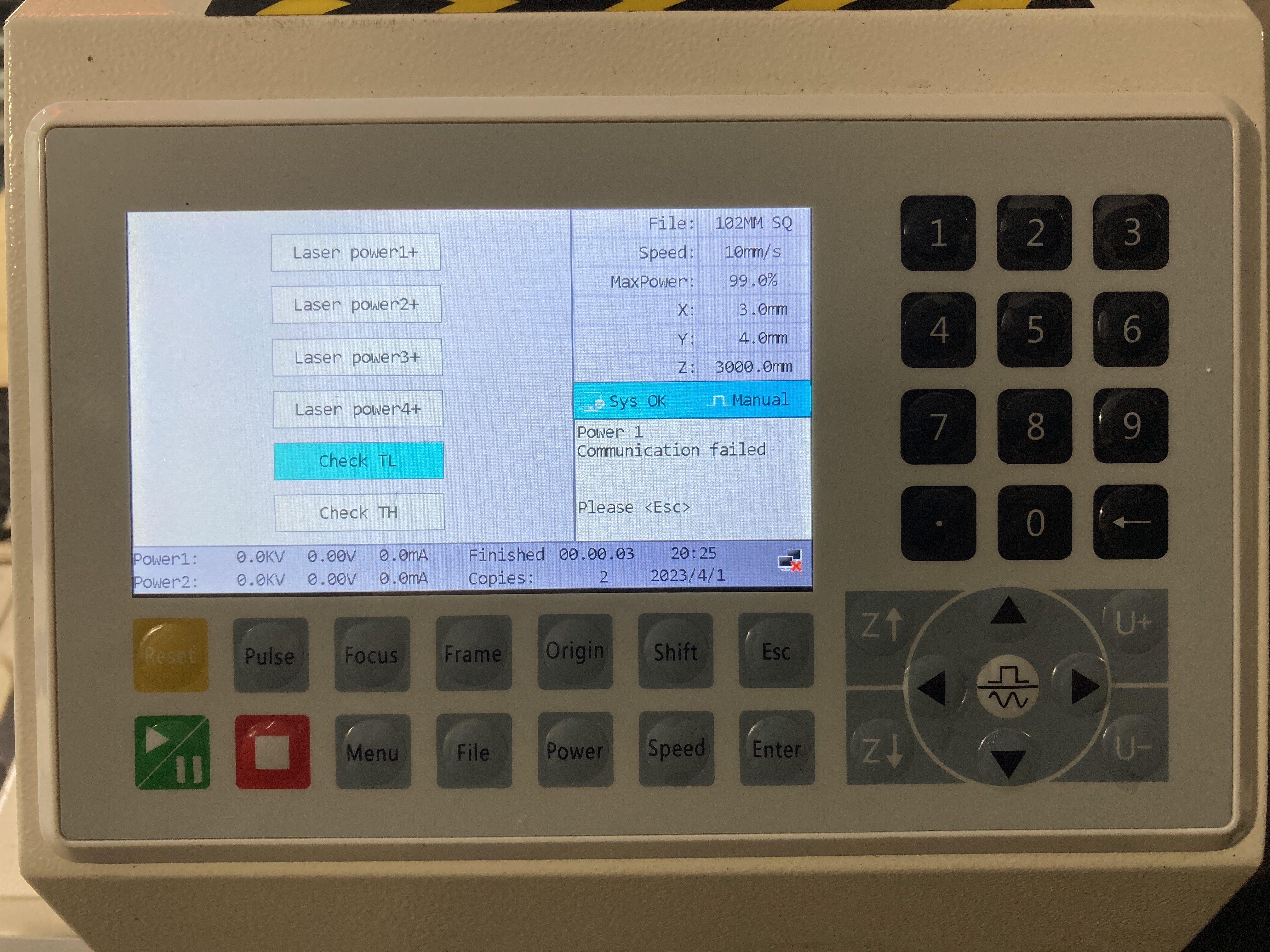
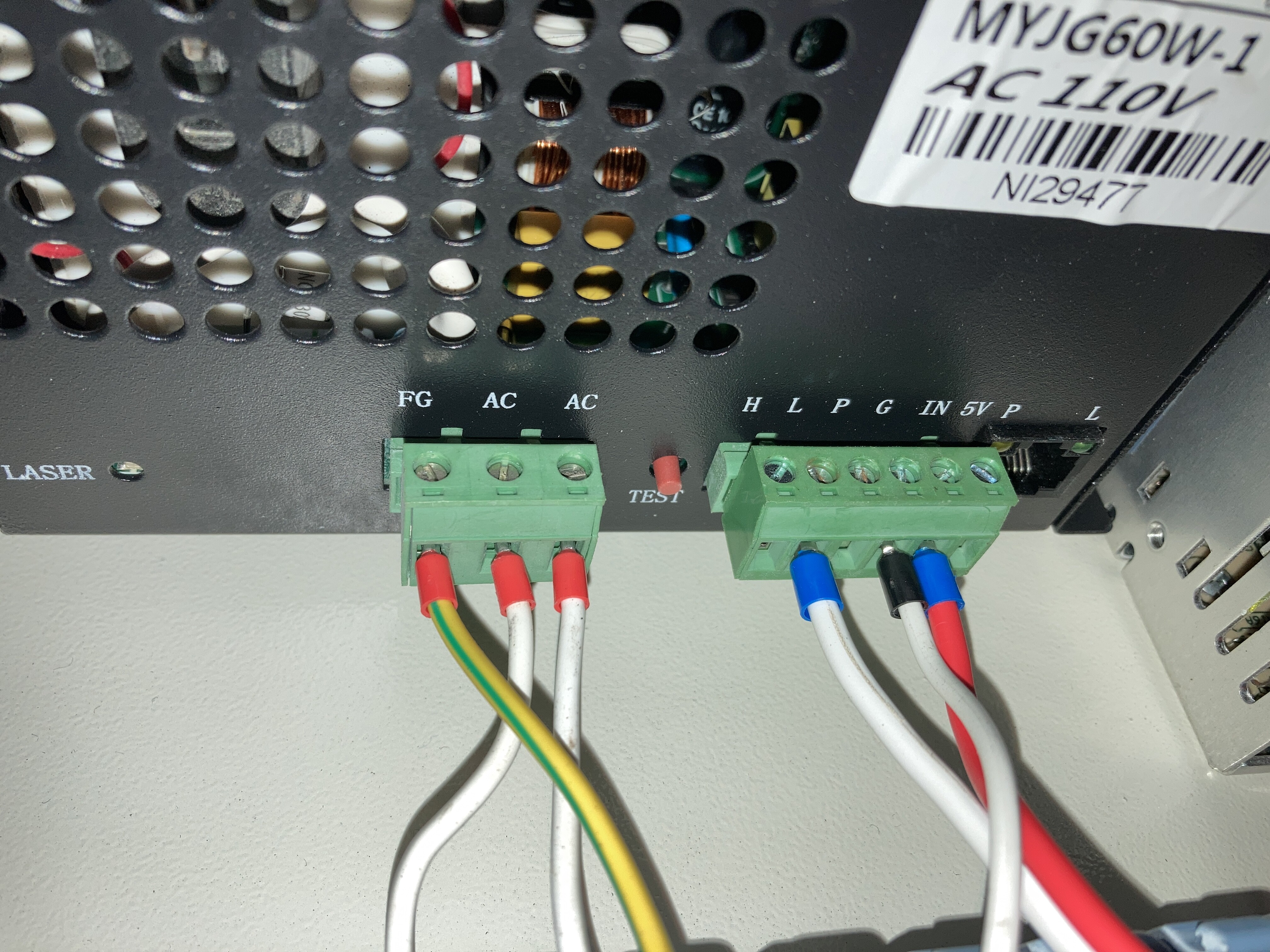
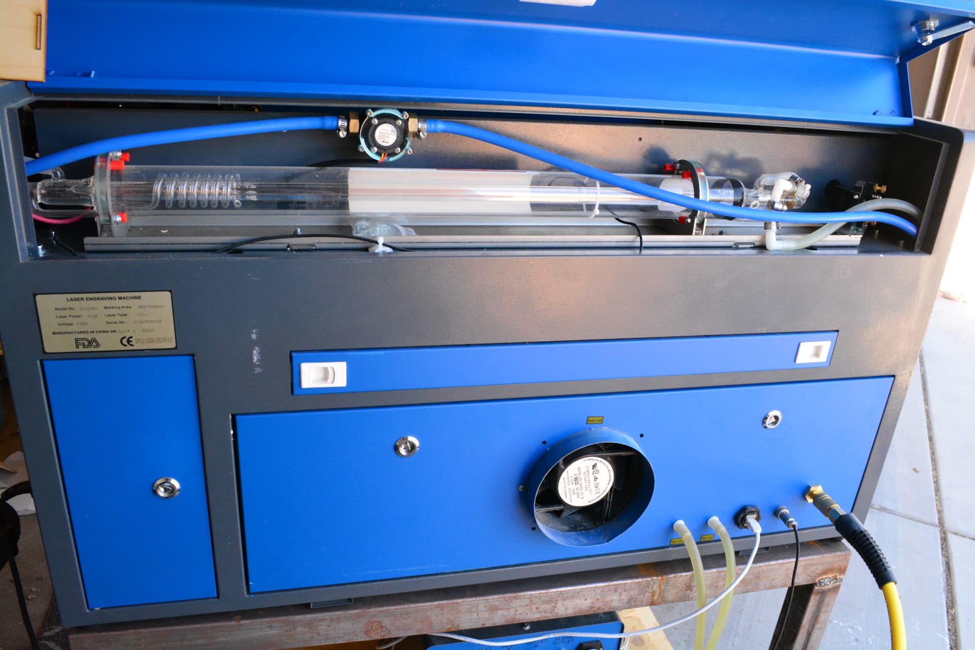
It won’t lase with the P terminal floating.
You have no water protection setup, which is the purpose of the P terminal.
However with a Ruida you should run your water protection to the WP terminal of the controller and let the Ruida control the lps. This probably has to be enabled within the Ruida.
The reasoning is simple… if the P terminal is used, it will just disable the lps from firing when the coolant flow fails. The Ruida will not know there is an issue, so the job will be lost.
If you use the WP terminal (enabled) on the Ruida and the coolant fails, the Ruida will halt the job. This allows you to correct the problem and continue, saving the material…
On my machine, the Ruida controls the lps, so the P terminal is just wired to ground.
You need to ensure you have proper coolant flow anytime you cause the tube to lase. It’s lightning in a bottle, so it generates lots of heat even a simple pulse can create too much heat without coolant flow.
I don’t know what the issue here is… can’t really suggest anything off hand.
Good luck
![]()
Set the XY axes for 400 mm/s with acceleration around 3000 mm/s², set the various Cut values maybe 1.5× those, then start tinkering.
Boost the acceleration until the motor stalls when starting or stopping a motion, then cut it in half.
Boost the speed until the motor stalls at the middle of fast moves, then cut it back by 25%.
The values will be different for the X and Y axes, due to the different masses involved, but will be similar.
A stalled motor sounds horrible, but will not damage anything.
Enjoy!
Thanks Jack!
Couple of quick questions.
Thanks so much for all your help.
Okay. I’ve re-read that again. Sounds like you suggest I do the following:
I wonder if ‘lps’ stands for “Laser Protection System” perhaps?
Thank you so much Ed. It’s good to have a formula to go by finally for trying to dial in the speeds. I’ll try that! Thank you.
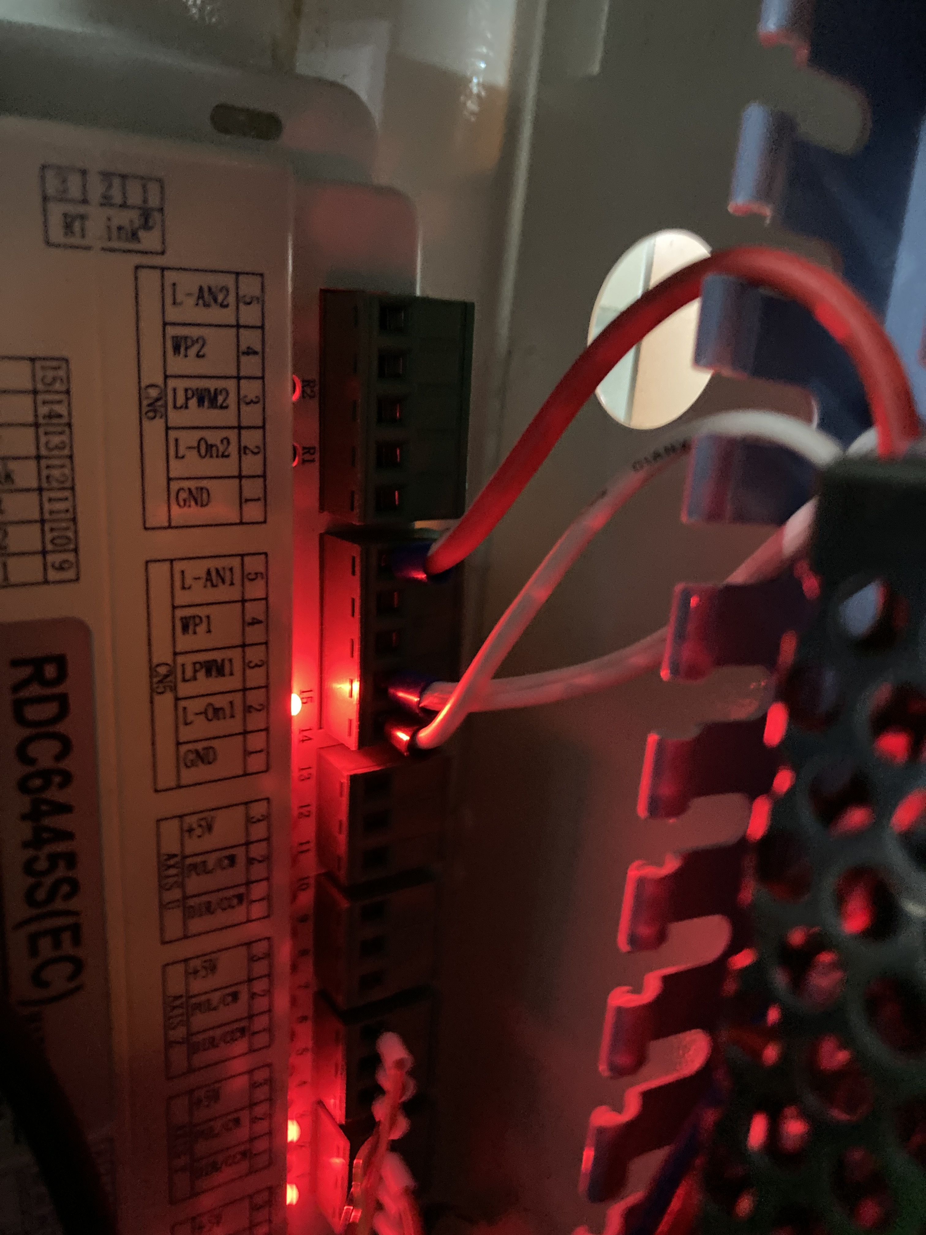
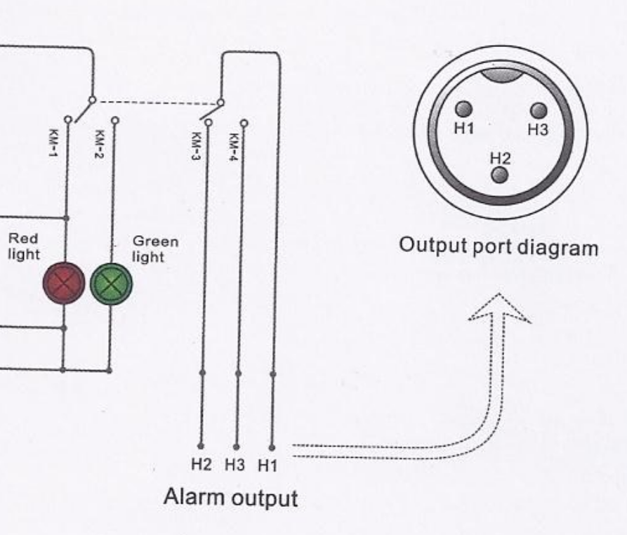
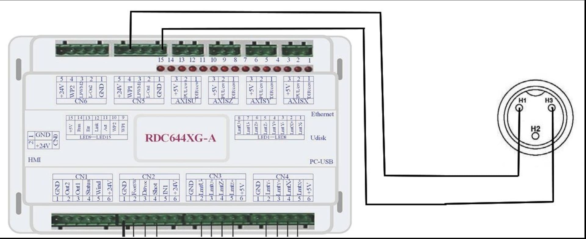
Connect your CW-5200 to your machine… Generally H1 goes to ground and H3 goes to WP1 on the Ruida.
Yes, wire P of the laser power supply (lps) to ground. lps is usually the high voltage supply…
If you want something that tells you what the flow is, you will have to build it from an Arduino or something. There is no option on the Ruida for a flow meter… I have one on my machine and a small micro to interpret it’s output…
In the Edit → Machine Settings
A quick explanation of why mine is disabled… My Ruida WP input failed. I do not use the door protection, so I moved the WP to the door protection input… Either will stop the machine… So I do have coolant protection… the console says it’s a door open protection error, but I know it’s a coolant issue cause it’s wired that way…
You will have to make a place to connect the WP to the CW-5200… Mine is between the air hose and the Ethernet port… you can also see the flow meter mounted over the tube…
Make sense?
![]()
Thank you Jack. You. Are. Awesome. You’ve been the most helpful person for me on this. Thank you.
I was doing a bit of research before I saw your reply above. I found this article stating similar directions:
One point of clarity I want to ask about is the H1 and H3. Their article seems to indicate the opposite. H3 goes to ground and H1 goes to WPA1. Is that okay or it doesn’t matter? Either way works?
Look at what’s happening…
You have a solenoid in the chiller that closes when it’s operting properly.
So if one is line is grounded and the other goes to the Ruida, activating it will always pull the Ruida input pin to ground. No matter which is which.
The reason I suggested that H1 to ground is simply this. A relay routes a signal. It goes in a pin, H1 and that signal is switched between two output pins H2 and H3… The input signal, ground in this case, is switched between H2 and H3.
H1 is the input, H2 and H3 are the outputs.
Active H3 is pulled low, inactive H2 is pulled low. That’s it…
If you reverse it, like your post, you will be connecting H2, which is floating, to WP… not a good idea, although here, it probably won’t matter…
Either will work…
Good luck
![]()
Thank you Jack. I got it working yesterday. Feels good!
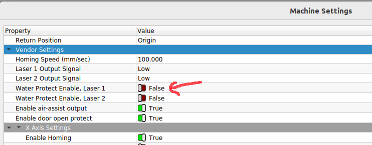
One quesiton though. It will lase even with the Water Protect, Enable, Laser 1 = False.
I’d forgotten to enable this after connecting the ground to P, and H1 to ground and H3 to WP1 as you instructed. Why might this be? And that means it’s not really protected, right?