I’ve been burning for a while and I can’t figure out why my machine is creating these evenly spaced lines within my photos. I am running a bachin 5.5w laser with grbl controller. Lightburn 1.0.04. My DPI varies from 0.13-0.09 depending on the image and I mostly use Jarvis dither. I have tightened and replaced both Y belts recently thinking that’s the issue (it was not). I believe it’s related to my Y axis as they are always perpendicular to it. Here are all my $$ values.
$0=10
$1=255
$2=0
$3=2
$4=0
$5=0
$6=0
$10=0
$11=0.010
$12=0.002
$13=0
$20=0
$21=0
$22=0
$23=0
$24=25
$25=500
$26=250
$27=1
$30=1000
$31=0
$32=1
$100=50
$101=50
$102=800
$110=5000
$111=5000
$112=500
$120=1500
$121=1500
$122=200
$130=2000
$131=2000
$132=200
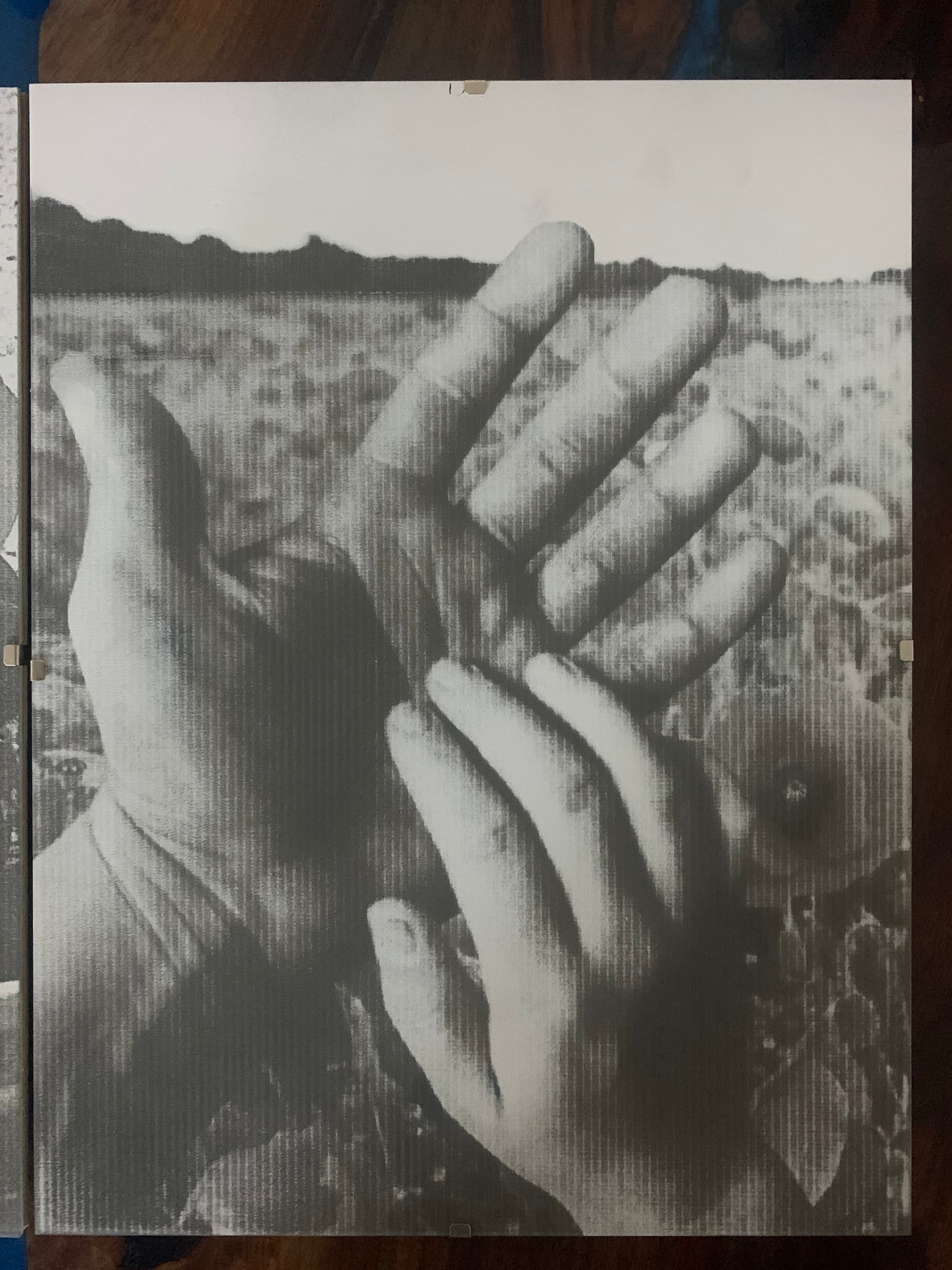
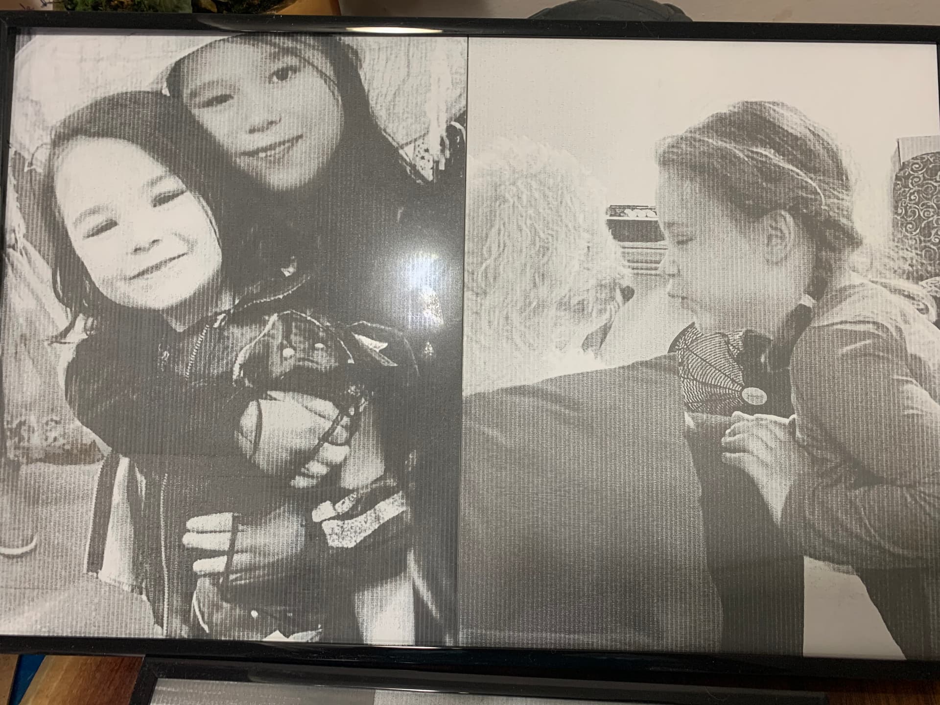
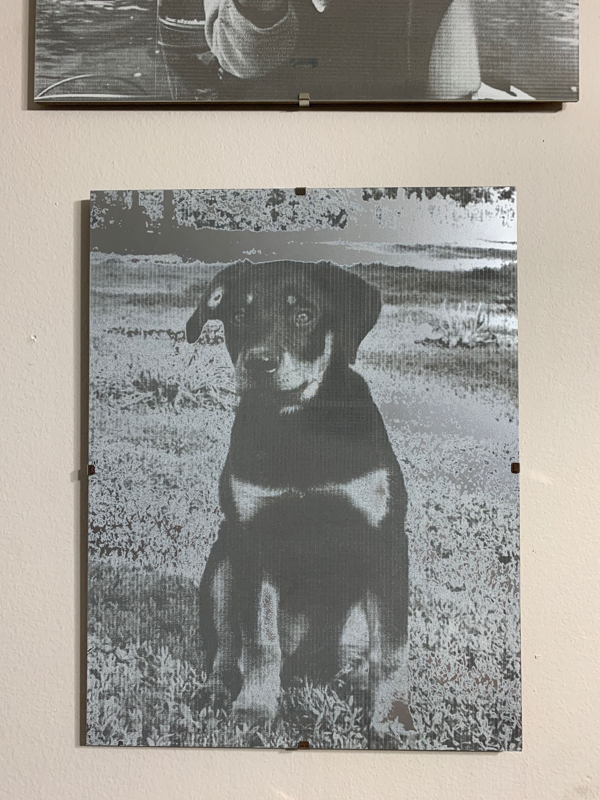
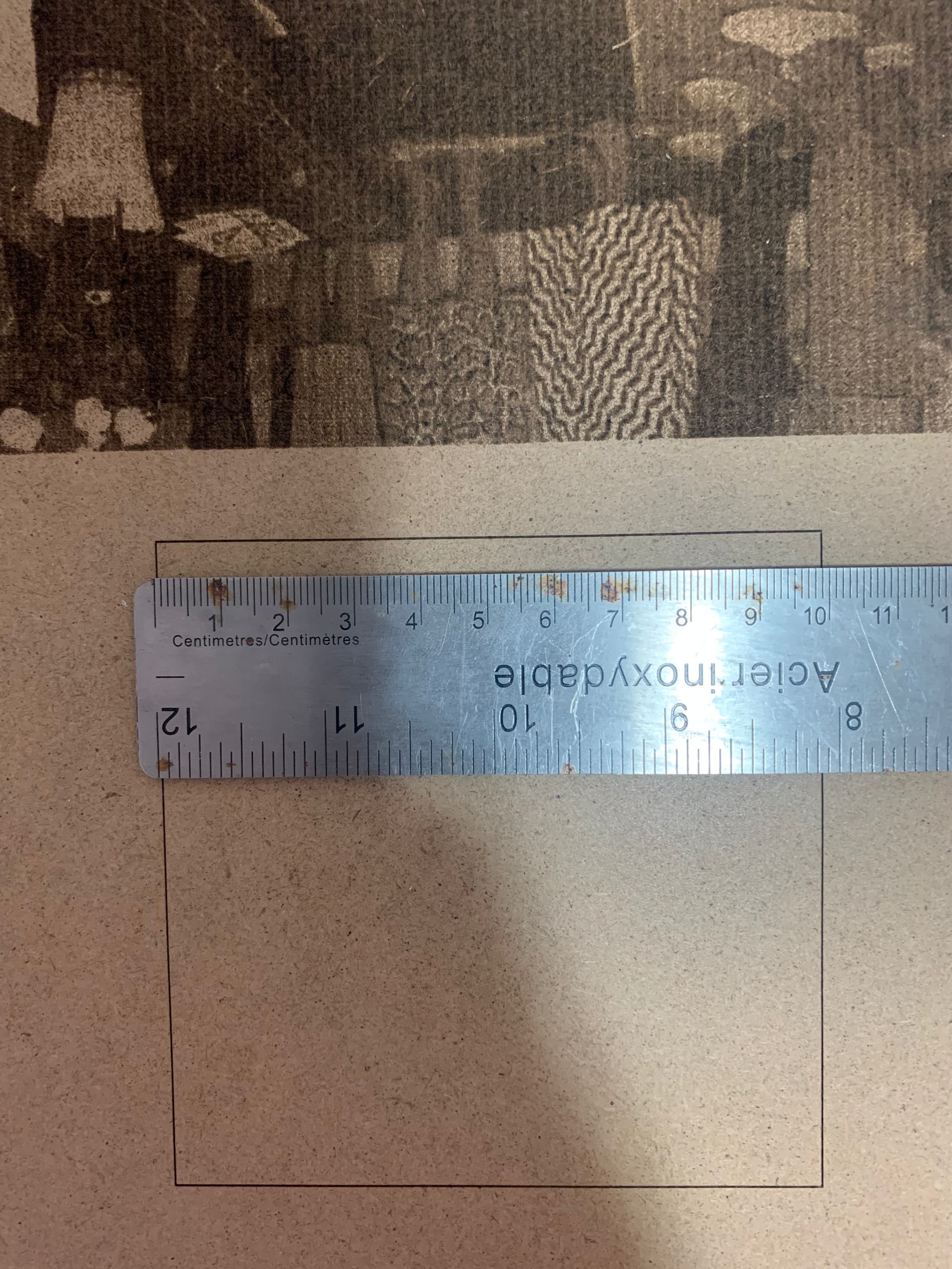
Here are a few photos of my work on glass. The spacing/banding is roughly 2mm.
Looks like ‘curtains’ to me, but I didn’t think your machine has belts.
I’d suggest you check how snug the wheels are to the rails. Most of these are on a offset post so turning them will tighten and loosen the grip to the gantry.
I would think there is some documentation on ensuring those are snug.
The bands are parallel to the Y axis. So anything landscape was engraved lengthwise as were all portrait images. Yes that is the line interval, .09-.13. The scan angle was 0 degrees but the lines show up regardless of the angle. This box was meant to be 100mmx100mm. Looks very close to 10x10.
Sorry. Had a typo in that question. I meant to ask if you had tried this with other image modes.
This is probably the most telling to me. This to me indicates that this is not an electrical issue as you’d expect this to shift in that case. I don’t think this would be anything software related as I’d expect the issue to be more uniform. Although it’s possible that the line interval and image mode could exasperate the problem.
Your observation that the band intervals match the teeth intervals is interesting but curious why it would affect the X-axis but not the Y-axis. Right now I suspect some sort of wheel wobble on the X-axis gantry. Can you check to see if the wheels on the laser assembly mount are smooth and uniform? Are the wheels held snugly (but not tight) against the gantry rail? If not, adjust nut to close any gap or loosen if it’s too tight. The laser should move securely but freely throughout the bed but in this case especially along the X-axis.
One final thing, have you run the Interval test in LightBurn to check for optimal interval settings? Might be worth trying.
Also, have you noticed any change in behavior with different engraving speeds?
Also, have you tried running in constant power mode to see if that makes a difference?
I have tested in stucki as well as grayscale using a variety of speeds. Always results in banding. The laser moves along the x axis smoothly. No loose screws/nuts.
I suggest running a series of tests in order to gather more data:
try running some test patterns designed to reveal mechanical issues. Perhaps a grid closely spaced vertical and horizontal lines; try running this at fairly high speeds to reveal any mechanical weaknesses.
run the LightBurn Interval test to identify ideal interval size
check a burn using constant power to see if that changes anything
Here is the Russ Sadler video of his ‘fix’ for the curtain problem… < 19 min…
@Burn, Here is a similar issue, might read through it and see if there is any kind of relationship that’s applicable. This is a 50watt co2 with a similar issue with a different type of banding. There was lots of suggestions…
That’s an interesting video and could tie-in to the 2mm teeth pitch theory. I suppose a simple test could be to swap out the pinion on the pulley to a different sized one. Or if this controller/stepper combination allow for switching the number of microsteps that might remedy the problem.
That would be a mess, since you would change the scale on that axis.
And it would still have the same problem when it rides over the ‘teeth’…
There is no ‘simple’ solution to the curtains issue…
Not a wizard on the micro step game, but from what I can determine, it’s probably less of a return. When you go to micro stepping, your available torque for a micro step drops significantly compared to a regular step. Usually end up with less accuracy. All of this is the ‘engineering tradeoffs’ we all put up with…
My fundamental understanding of the problem may be incorrect. I had understood it as essentially the harmonic overlap of the teeth on the belt and step size. My thought was that by slightly offsetting that relationship by increasing/decreasing the pulley size that the harmonic effect would be avoided. Step-size recalculation would easily remedy scaling impacts.
However, again, I might be misunderstanding the root cause.
Either way I’m thinking there must be a simpler way to avoid this than Russ’s rack and pinion solution as other traditionally belted systems don’t exhibit this and even on this laser the Y-axis doesn’t show this.
If this is fundamentally about acceleration/deceleration as caused by tooth geometry on the pinion then I’d expect to see a couple of things be true:
less of an effect at lower speeds; low enough speeds should make this almost disappear
dissipation of the vertical bands gradually as the scan angle increased to the point it disappeared at 90 degrees since X-axis acceleration would be negligible since it’s only moving one line at a time.
However @Burn has stated that this doesn’t change based on speed or angle.