@jkwilborn do these help?
@stixstudios excuse me? Troll?
@stixstudios I hope you aren’t calling me a troll!!!
Nope it is still happening. Like I said, I tried everything. Rewiring the entire machine, putting filters on the power plug, ferrite filters on the signal cables, different computers, different outlets, grounding, lifting grounds. The list goes on.
I’ve pretty much given up for now. I’ll try and mess with it tonight to see if maybe the stars will align. This problem is definitely not mechanical except for maybe the tube rattling the beam somehow from X axis changing positions.
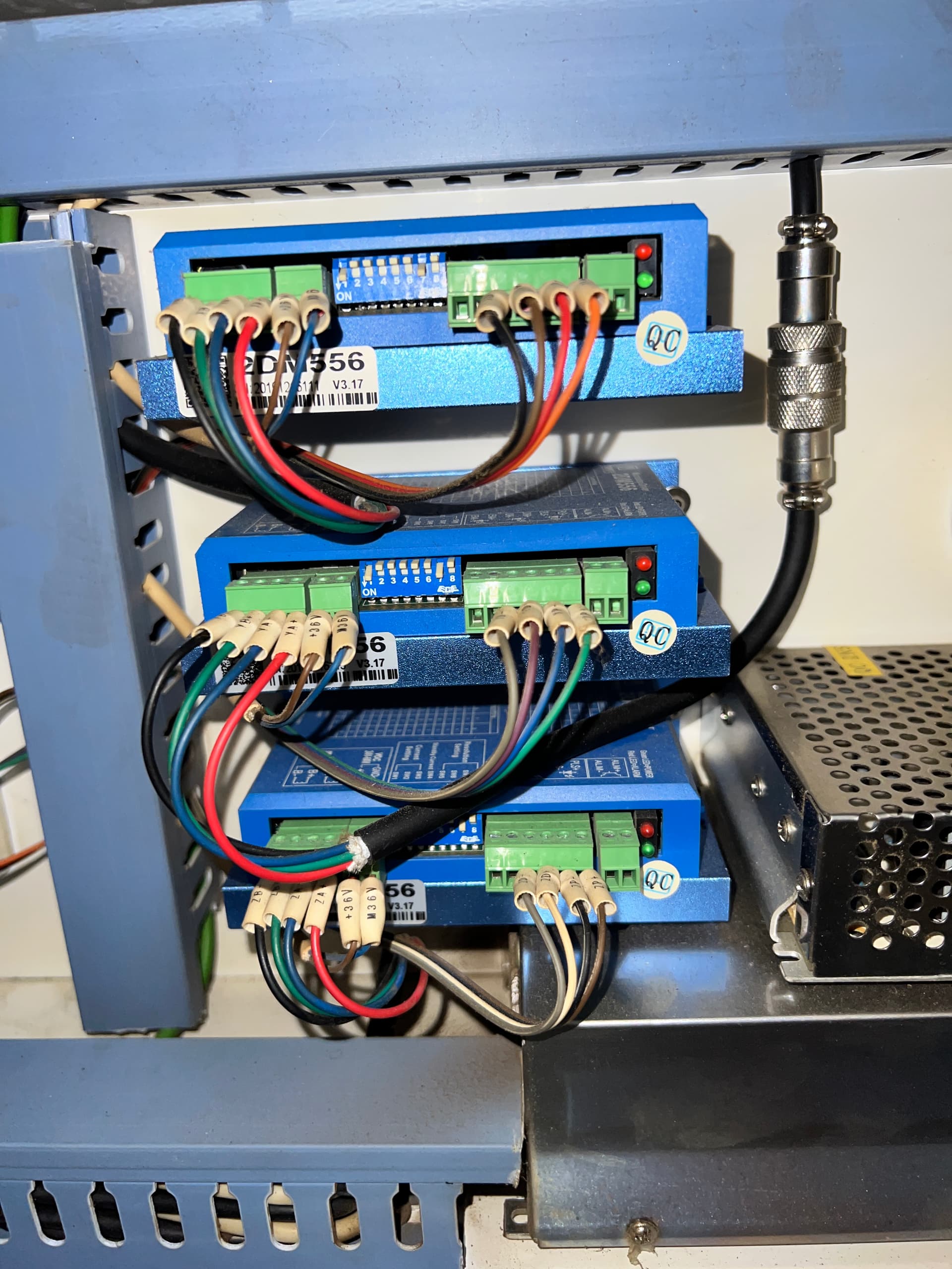
Do you know what motors you are running? You can measure them. Mine are NEMA 27, meaning they are 2.7 inches across the square part.
You motor drivers are set to the minimum, current wise…
Unless we can get it to ‘fail’ long enough to id what’s failing it’s going to be the devil to figure this out.
![]()
Hence the reasons why I had asked for drawing some thick vertical lines and setting up a controlled test… After the vertical line tests the next test was going to be horizontal lines and changing the Scan Angle to 90 deg so it’s the Y motor doing all the acceleration/deceleration.
A more direct test would be to put an oscilloscope on the 24V and 5V lines but not everyone has those tools or skills so other means of eaking out the problem have to occur.
The problem with scopes and intermittent operation is that what do you trigger on?
Since the firing is apparently random.
You could probably set a low voltage as a trigger…
The other issue is that there is 24 volt motors and the control going to the lps are low voltage controls, ttl levels.
It’s hard to imagine the 24v motor supply being able to be loaded down to cause a logic low on the lps enable pin, @ < 2 V.
Let alone maintain it’s step rate and keep the Ruida alive.
@kimmicks07 … shot in the dark, how does the output of your tube look at mirror 1 (m1)?
Looking for a tem0 state.
![]()
I’m not looking to catch the dots, looking to see if there’s anything on the 24VDC or 5VDC which might indicate an issue. That looks like a small laser cutter so it probably does not have a separate 24VDC for the motors like a K50 or larger machine would have. Therefore seeing if there was a dip in the 24VDC or 5VDC might indicate a bad motor. It’s a very quick glitch so I would expect the Ruida to have filter caps which probably holds it up during the glitching supply.
That’s my theory and right now since everything has been replaces but the motors and wiring.
According to Kimberley, it is a 50 watt Ruida controlled machine.
Since the Ruida operates on a 24 volt supply, I don’t see how it’s possible to pull the Ruida supply voltage down to a few volts, required to fire the lps, and not re-boot the Ruida.
It appears it’s slow enough for the lps to respond and mark the material. I think it’s within the operating range of the Ruida, so it can’t be suppressed without impacting the actual operation.
![]()
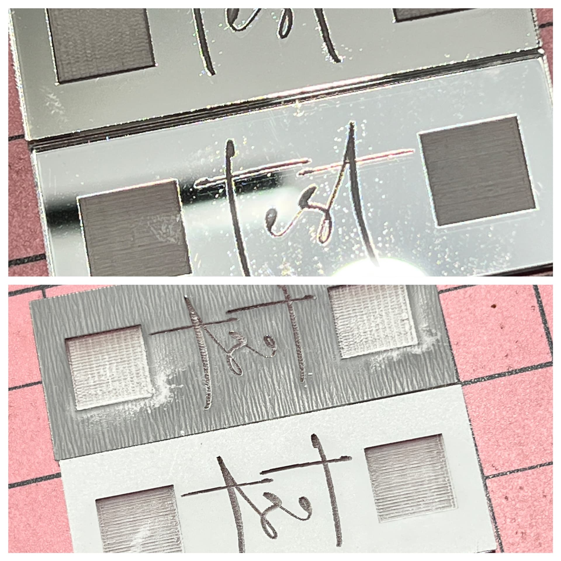
If you look at what the dots do when she slowed it down you’ll see they got closer to the text lettering and with 300mm/s original speed the deceleration distance was going to be far greater than the letter width. So to me, it looks like the dots are occuring on deceleration or more probable acceleration. Therefore I do not believe the Ruida is commanding the LPS to trigger for those dots.
I’m theorizing that the LPS laser firing circuitry is glitching possibly due to excessive loading of the 24V which is also where the 5V is sourced from for the LPS trigger circuitry.
1 Like
The Ruida runs on 24 volts. The ttl output would have to not only fall below 2.5 volts or more, but it would also have to actively ‘sink’ the 5v supplied by the lps on the L input.
I’ve pulled the power on the Ruida and power the rest of the machine up… the laser does not fire.
If the output of the Ruida 5v internal supply fell below 2.5 volts, the Ruida would reboot when the power…
Also have to consider that the 24 volts is not applied to the motor, but to the motor driver and her motor drivers output is limited to minimum current. This effectively isolates the motors from the supply, at least how you are referencing them.
If you can figure out how she can test this theory, please explain. She’s tried lots of things…
![]()
1 Like
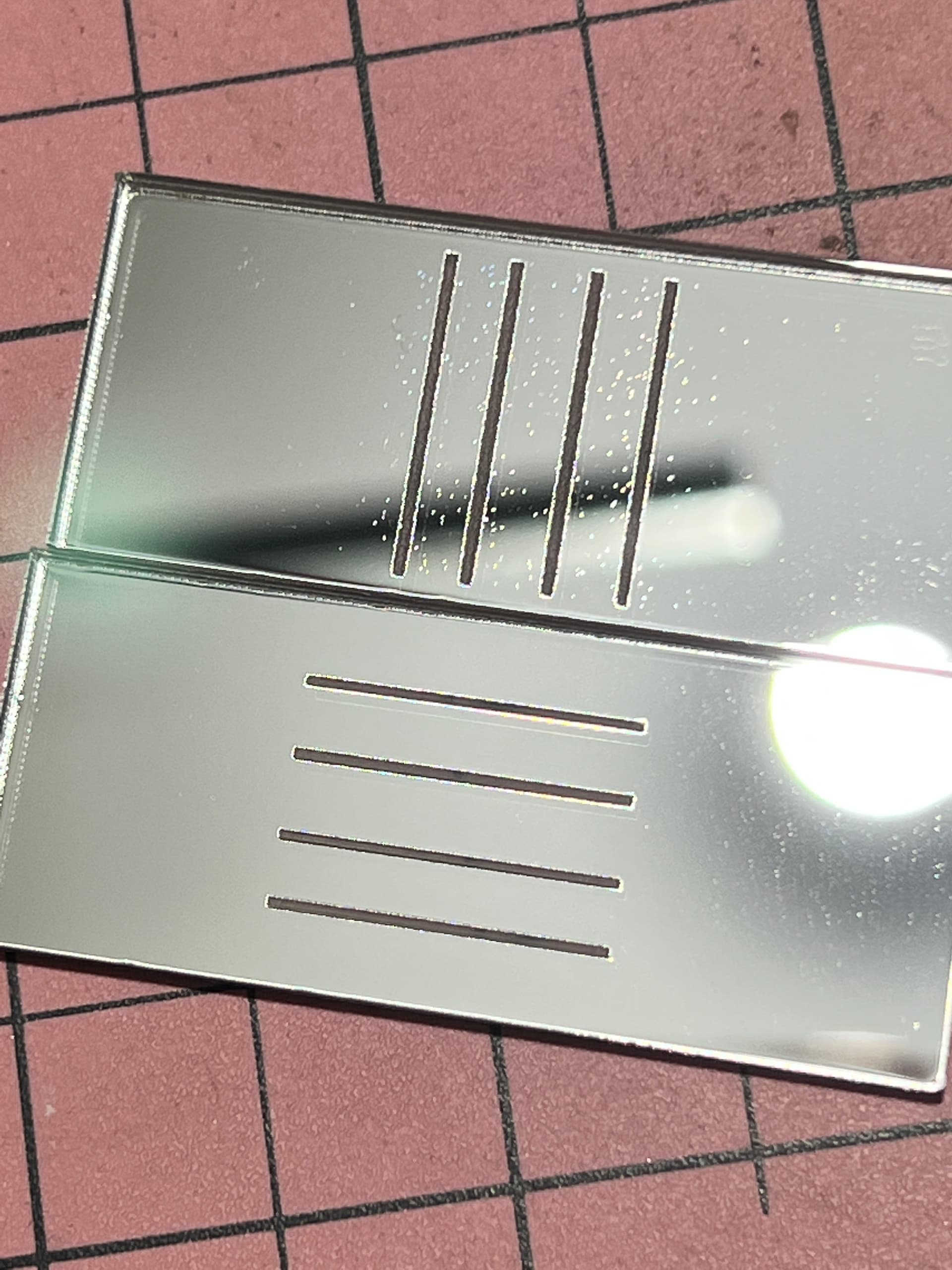
she isolates it to a motor by doing the tests I mentioned… vertical lines the same width as the “t” in the text she’s using. Mentioned 4 lines spaced out as her text is just to keep it consistent. Run it at 300mm/s like her text and see dots. Rotate the lines 90 degrees to make them horizontal and then rotate the scan option by setting that to 90 deg and run the test to see if the dots now are translated to the vertical axis. If not then it’s associated with her X axis and likely axis motor.
Heck, replacing the X axis motor is far cheaper than many of the other things she’s already replaces.
1 Like
a K40 LPS has a very weak 24V output since they ONLY have to drive a 0.8A motor(X axis) and 1.2A motor(Y axis) and a K40 uses 400 step/rev motors. If they used the same cheap LPS and are driving higher power motors, with 200 steps/rev AND powering the Ruida+display… it could very well be on the ragged edge and especially so when a motor bearing starts causing the driver to max out current draw. $0.02
@Bklynghost sorry to hear it’s still playing up for you. It’s soooo frustrating hey. Like makes zero sense!
@DougL im going to try this in 10 mins. Stay tuned!
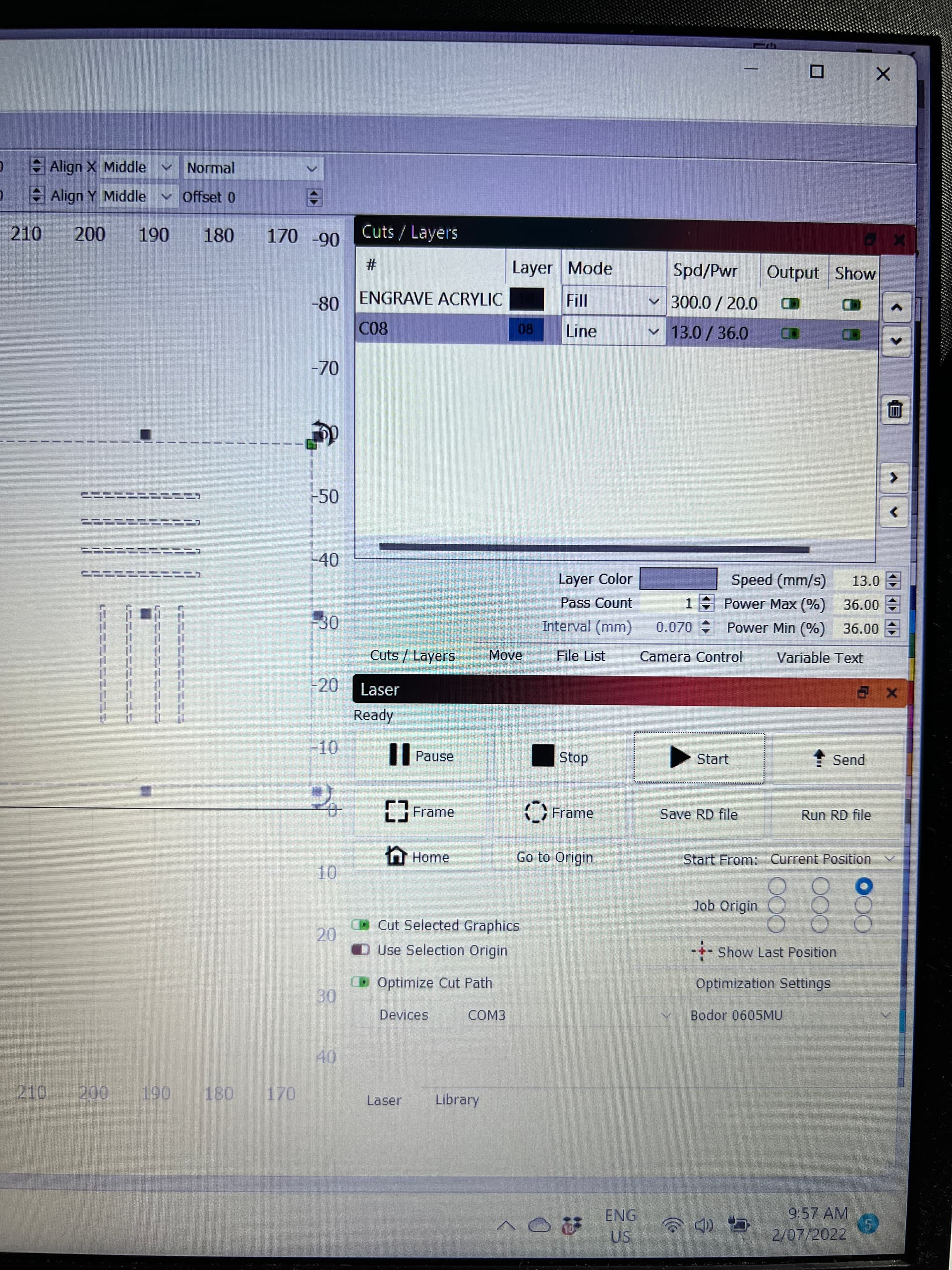
@DougL like this?
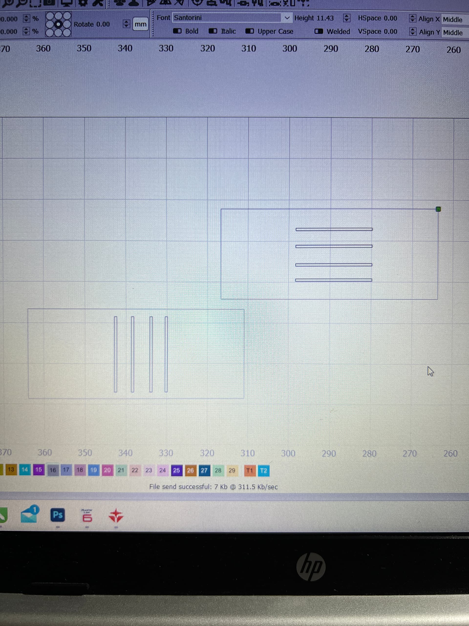
Not sure why the outside box, it should be just the 4 lines and you need to set them to fill just like you did the text. EXACTLY like you did your text. Maybe post a pic of your text Cut/Layers page and post the pic of the Cut/Layers for the 4 vertical lines? Do the vertical lines first and they should process just as the text did, ie one line at a time, top to bottom or bottom to top.

If the horizontal lines were scanned at 90 deg( ie scanning was along the Y axis ) then I suspect the bearing in the X axis motor is worn. You might try loosening the X axis belt just a little bit to see if that changes the effect on the vertical lines. The belt tension will cause more binding on the bearing so loosening the tension should also change your dots. Even if the dots go away, I would still rebuild the motor. You might be better off replacing it unless you are good with tools.