@DougL I haven’t no… that’s a good idea though. The controller was replaced (then old one put back in) so I’ll have to see if there is anything in the controller memory ![]()
1 Like
@Bklynghost damn, and still no fix? sorry to hear! do you have a work-around, or do you just not engrave mirror and leather etc now?
It’s a 50w (60w PSU) white/blue machine with a genuine 6442S-B controller. Checked the ground continuity between the machine and a different outlet, on the same breaker all is good there. I might try running a separate ground to the radiator, running out of ideas here.
2 Likes
I mostly use the laser to cut parts, so not the biggest deal. I do some engraving, but it is on forbon which then gets wax potted and that takes care of the dots since they are not burned in at full power. if I do have to engrave acrylic, I leave the protective paper and the dots don’t make it through. it’s become an OCD thing for me trying to fix it, otherwise it doesn’t really affect my work.
1 Like
IIRC those machines have an external 24V power supply which is used to drive the Ruida controller and the stepper motors. Does your machine have a separate 24V PS?
Sorry,
Yes, both the motors and the controller are on the same power supply. I actually have another one, I’ll run the controller from the second one right now.
1 Like
@kimmicks07 @Bklynghost when you guys ran this test and you got dots on only one side of the lines, what was the engraving action? ie Was it doing bi-directional engraving? Was it sweeping across all 4 lines at once or was it engraving one line at a time. Seems odd the dots now are only one one side of the lines…
1 Like
Scanned the whole job.
Just tried the separate PSU no luck. I might try a different controller, I have a KT332N laying around.
1 Like
ok, so scanned but only in one direction or bi-directionally(default)? Seems odd the dots are only one one side for a bi-directional raster engraving.
Are you using the analog control or the digital control from the Ruida? IIRC, the analog control connects to the LPS-IN while the digital control goes to the LPS-L signal.
@DougL that was with bi-directional turned off as per a test recommendation from @NicholasL
It was doing all 4 lines at once
@kimmicks07 ah, ok so really no different from the other things. The only interesting data point I’ve seen is that the dots get closer to the engraved line when the speed is lowered. I thought for sure it was somehow related to acceleration/deceleration.
1 Like
I had it connected to the digital pin L-On1 I switched over to L-An1 and it fires throughout the whole the job. Tried switching the settings to High and moving to H on PSU, but it’s acting weird and firing when homing. What would be the settings for the analog pin?
BTW different controller didn’t fix it.
The L-ON1 uses PWM( pulse width modulation) for setting the power level of the laser(50% duty cycle ON/OFF is 50% laser power ). But the analog input is voltage level based so another pin on the controller is probably needed for driving that. ie if it’s a 5V signal then 5V is 100% and 2.5V is 50% laser power.
I don’t have a machine with Ruida but I’ve seen lots of Russ Sadler videos to pick up a thing or two.
Wait, if you are using the Ruida analog output you need to connect it to the LPS-IN signal IIRC.
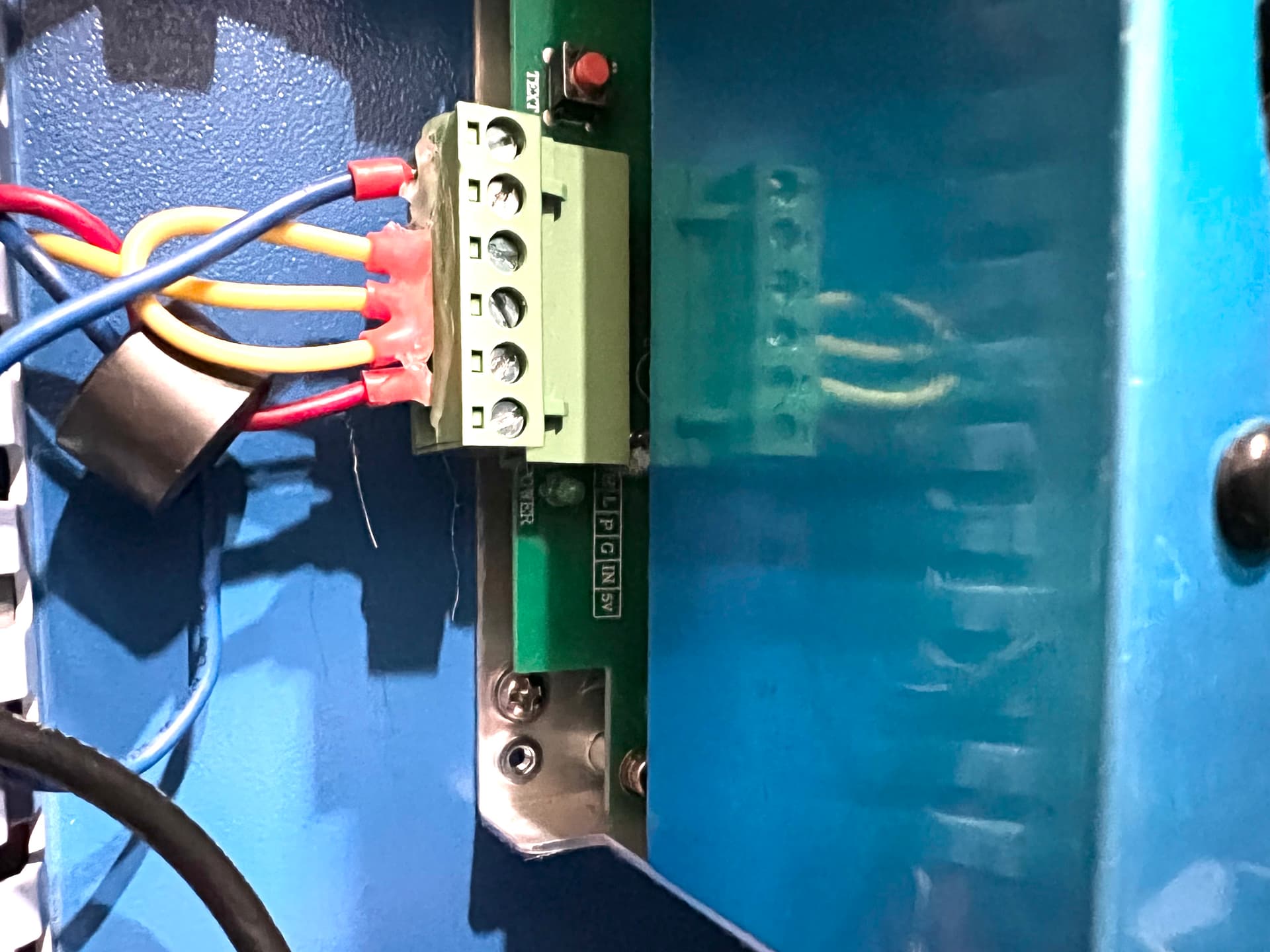
That makes sense. Looking at my power supply, the water protection has a jumper going to IN. What’s happening there? shouldn’t it be grounded?
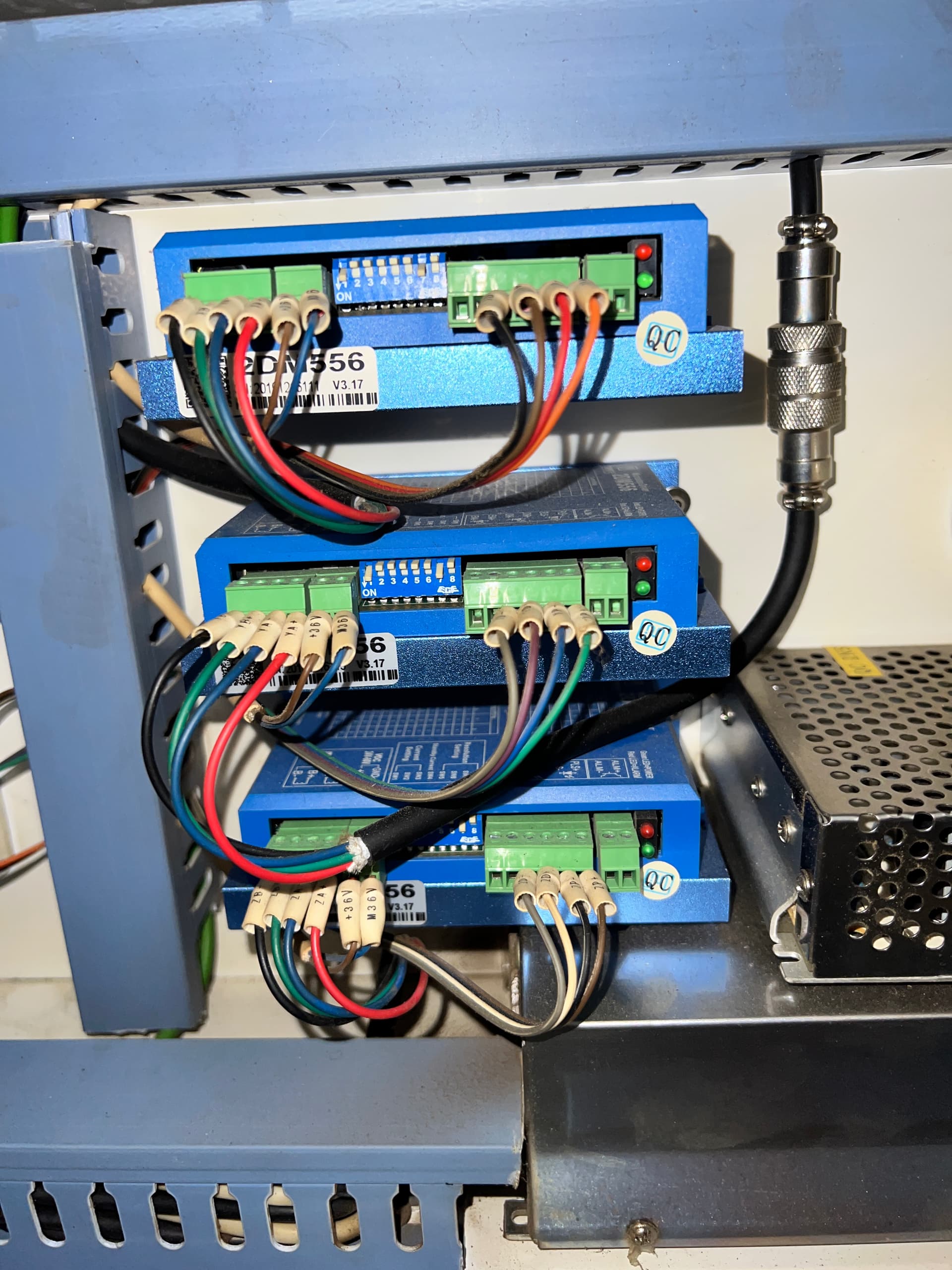
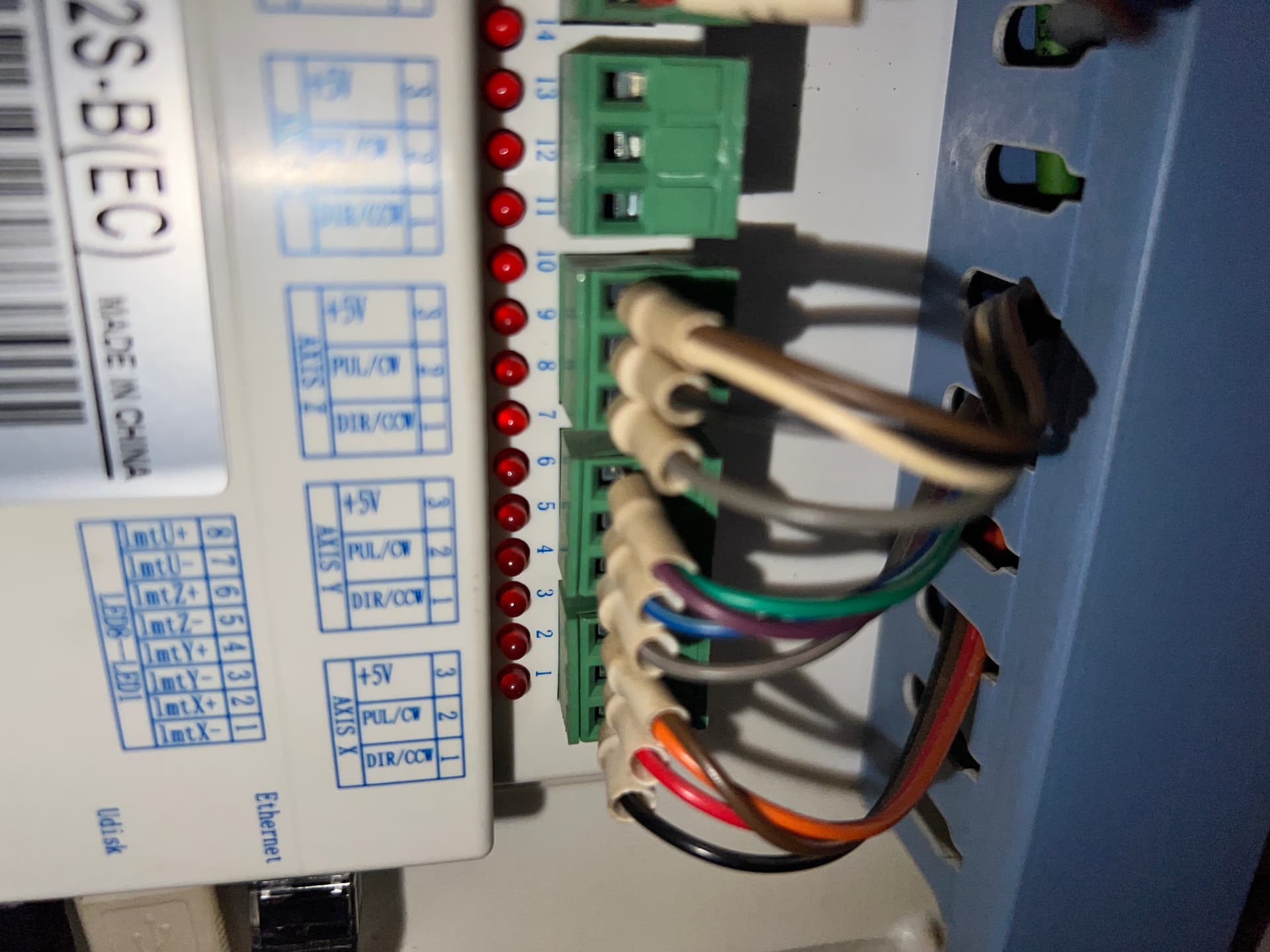
Those are all stepper connections. Could you take a picture of the power supply and laser control terminals?
1 Like
@kimmicks07 , Those look like they are all of your motor driver boards and the motor driver side of you controller. The other side of the controller is all about controlling the laser and the safety switches,etc.
1 Like
@Bklynghost generally the IN input is a voltage setting which determines the MAXIMUM output your laser can provide. On the cheap K40 machines, there is a variable resistor and the 2 pins on either side of LPS-IN are 5V and Ground. This lets you use a variable resistor to set what your maximum laser output power is and then use the LPS-L signal to pulse width modulate to vary the laser power output up-to the max set by the voltage on LPS-IN.
In your case, they just hardware IN to 5V so the Laser Power Supply(LPS) will put out max power and you probably have PWM out of your Ruida going to LPS-L. If you want to use analog control, which most Ruida setups use, then you connect your L-AN1 output from the Ruida to the LPS-IN signal on the power supply. You should be able to find schematics showing this. You would definitely want to remove that jump if you want to use L-AN1 analog output.
And L-OUT might have to be connected to LPS-TL which basically is like a laser enable signal.
Their manual sucks… it lists L-AN1 but then in their example schematic they don’t show L-AN1 but instead show it as a PWM label. But I think the connections are the same. ie Ruida-L-AN1-> LPS-IN and Ruida-L-OUT->LPS-TL
