Hi there,
I am looking to install a skr v1.4 into my k40 but i am just getting a bit stuck with the wiring .I have read the skr v1.3 write up that is on this forum but because they use a different type of psu than mine its just throwing me off lol.
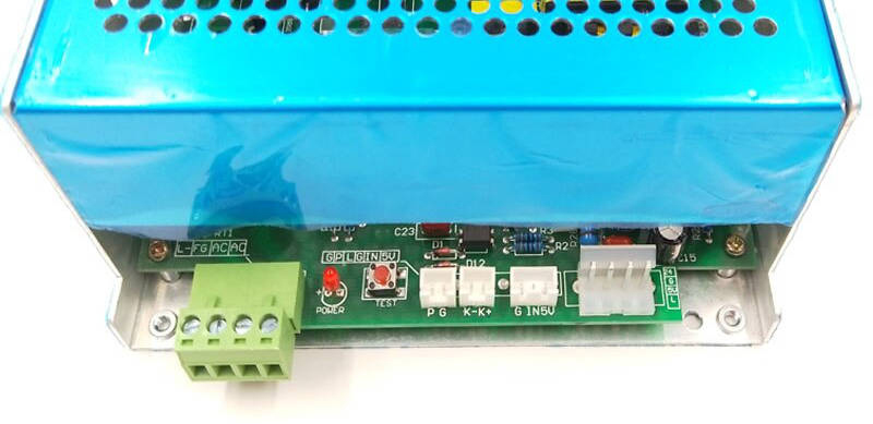
The psu i have is the one with the jst connectors
Now am i correct in thinking is all i need to do is connect the L wire on the far left to a pmw pin on the skr i.e pin 2.3 which is the fan - .
The 24v is coming from a separate power supply and i just disconnect the 5v and leave disconnected.
Also i flashed the cohesion smoothieware firmware.bin to the skr and since doing that the board wont show up on my macbook ,does anybody know why this might be please.
Any help is gratefully appreciated thank you Nutbox
Thank you ,that is the thread I have been reading but because the psu is different it has confused me lol.
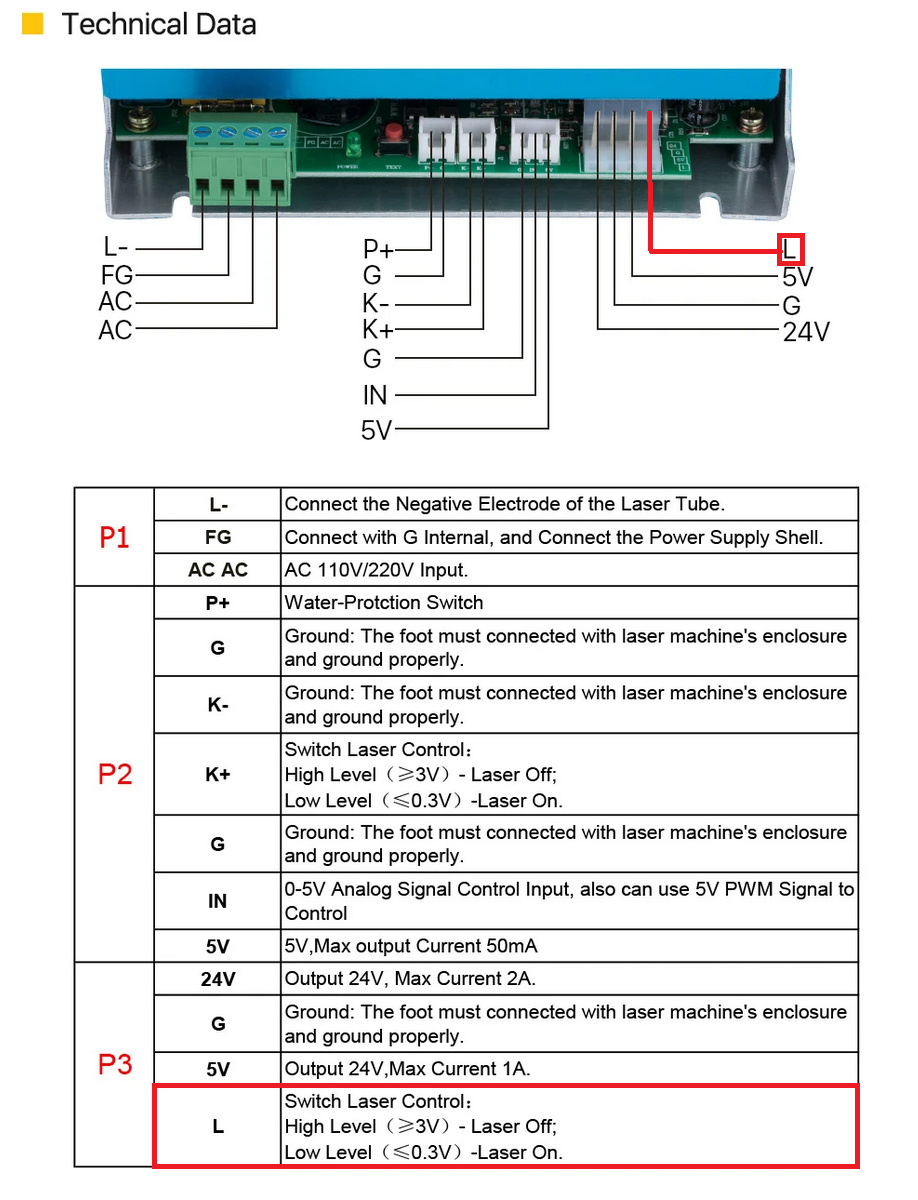
My psu only has the L pin and no laser fire or laser pwm but would the “IN” be where I connect the skr pwm pi to and laser fire to the L pin?
Hope that makes sense cheers
For some reason I keep thinking the K+/K- is the control input. Generally they have an L input, which is usually a type of ‘laser enable’ and the PWM control, IN to turn it on and off.
I have seen cohesion board just uses the L pin and the controls the laser max limit with the k40s potentiometer and then I see in the write up you link that the lasers min and max power is software controlled so that’s where getting confused.
If the controller supports it, you can set your max and min power levels and let the controller handle the cornering…
Don’t worry about max and min, just get it up and you can worry about details like that later. In all probability, it’s up to what control board you have.
Looks like the L pin is the return from the tube, where the ma meter might go.
The PWM goes to the IN connection of P2.
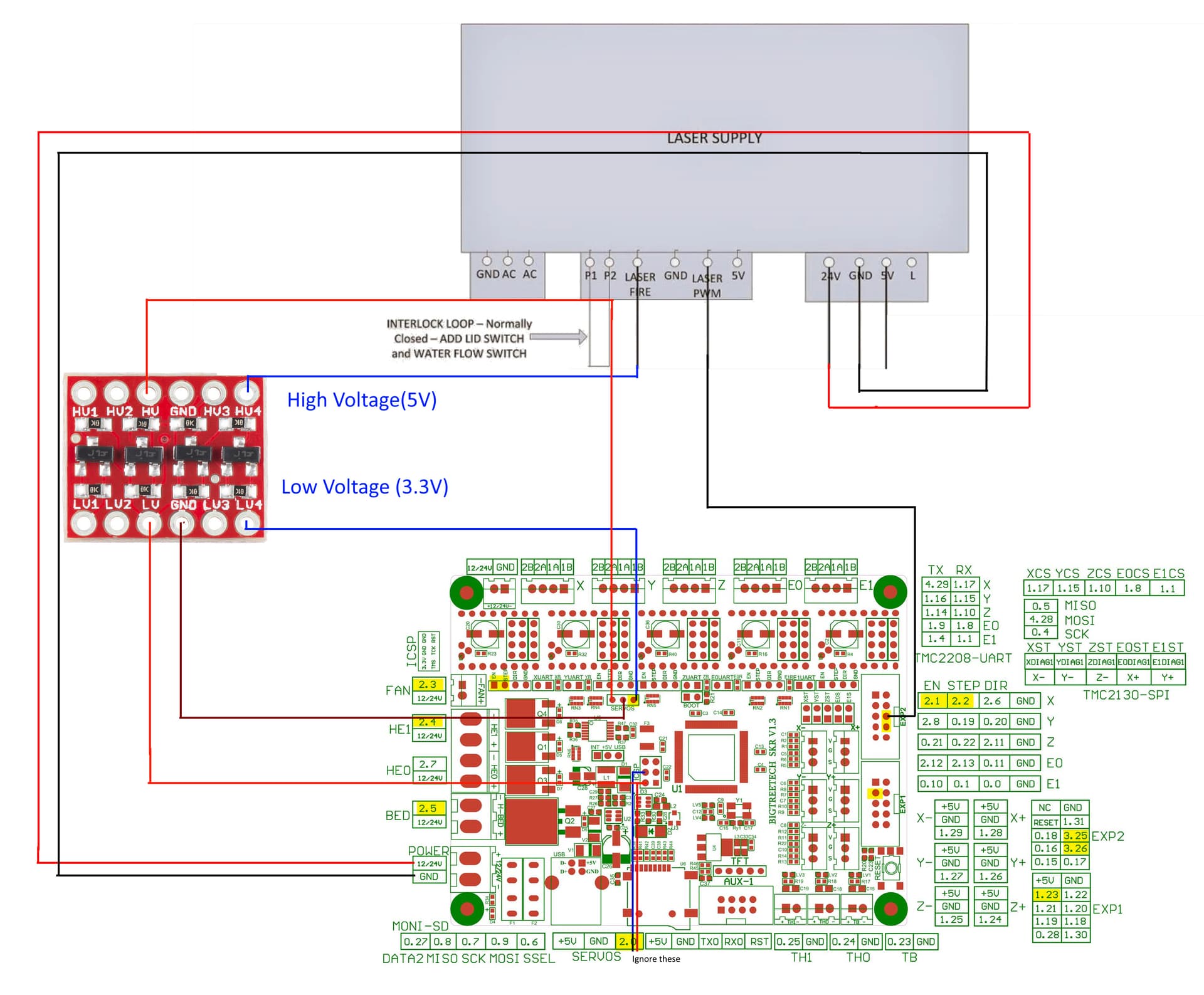
‘laser fire’ is the enable and it’s shown going through the voltage level translator. I would think you would use the L pin of P3 to enable the laser. And let the PWM control it.
The 5v is an output voltage, so you don’t connect to this unless you have a low current <50 ma 5v need. Such as the level translator…
Hi Jack,
I have got the skr moving the axis in the right direction and homing all good so now on to firing the laser.
Is it my understanding that as you have stated above is that the pwm wire should be connected to the IN pin on P2 and then the 5v from the logic level converter should connect to the L pin on P3 and the laser should work like the thread you linked me to and from this diagram
I’m just reading the diagrams. I understand how most of these work, but there’s seems always to be some kind of exception.
If you notice the K+ enables laser at a low level, L enables laser at a high level. On my supply, the H has the same operation as the K+ in that it’s the ‘inverted’ enable, so to speak. At least that’s my interpretation.
Apparently the signal coming out of your board is on a 3.3v system. I would think if you don’t need that converter for your pwm, you wouldn’t need it for the logic level of the ‘Laser Fire’ either, IMHO. Maybe someone can clarify.
Don’t know how much power and where you have it available, but I would think the level converter would require a very small amount of current and you could probably run it off the supplies 5v tap. It’s limited to 50ma.
ok i read some more of the post you linked me to and see squid is using just one wire which is pwm controlled so i thought i would try that but when i check the voltage coming from the skr pin it is around 20v i have tried inverting it ,pulling it down and open drain with not much change in output,i thought these pin were suppose to be 3.3v as you say?
thanks again
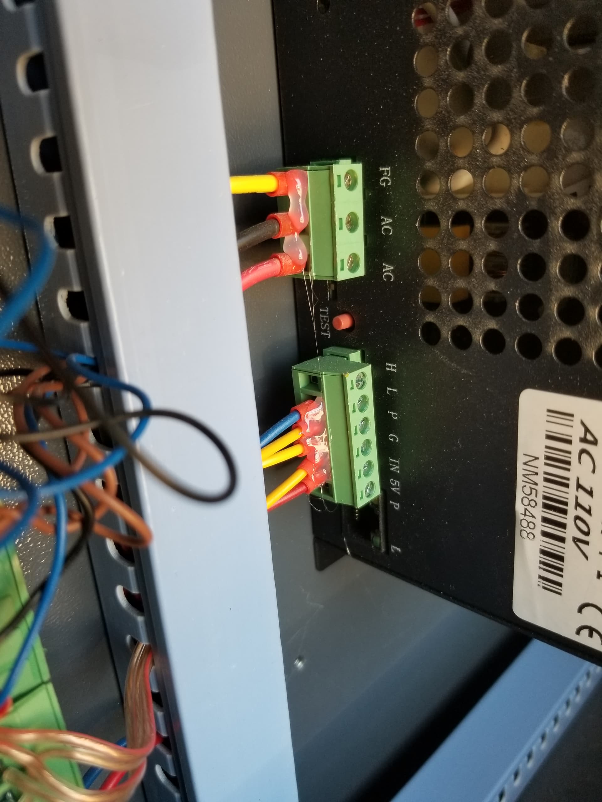
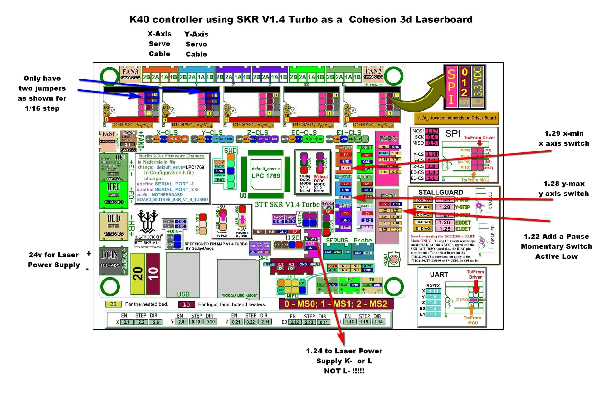
right more playing about today found another write up on installing the skr v1.4 into the k40 and it used one wire for the pwm signal to the L pin in P3 on the psu copied their config file and nothing tried numerous configs but then had a epiphany and added a ground pin next to the pwm pin i was using and connected it to the chassis and the laser fired up,so is this the solution?
Here is the diagram of how it wired up minus the ground which is connected to the ground pin of the neopixel connector.
From what I can gather is k- is supposed to be the same as L on P3 .
The thing that confused me is I thought the ground of the skr that’s attached with the 24v power to the board should of taken care 9f the grounding shouldn’t it?