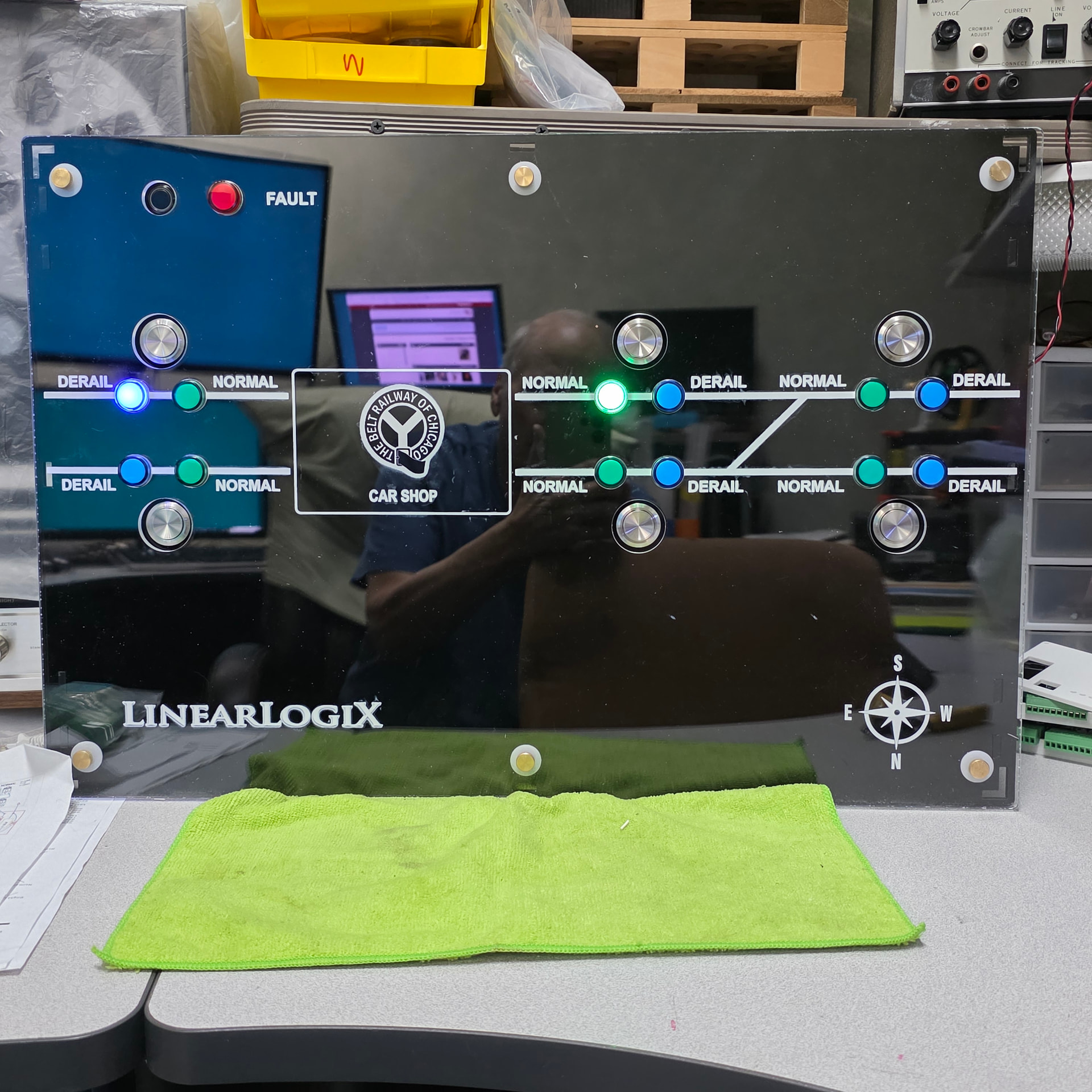
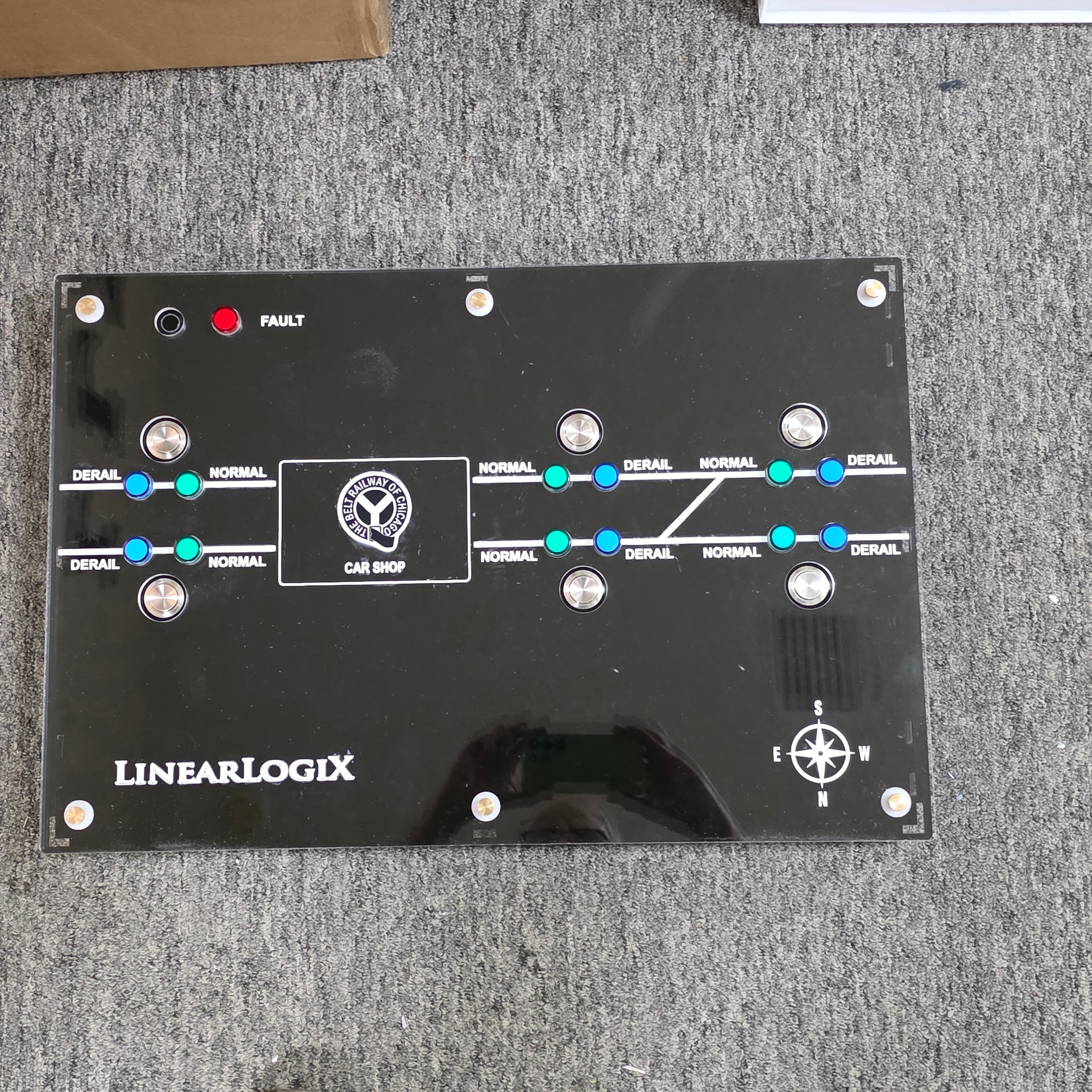
We finished a controller for a customer…
lots of acrylic cutting and UV Printing the front panel layout…
6 Likes
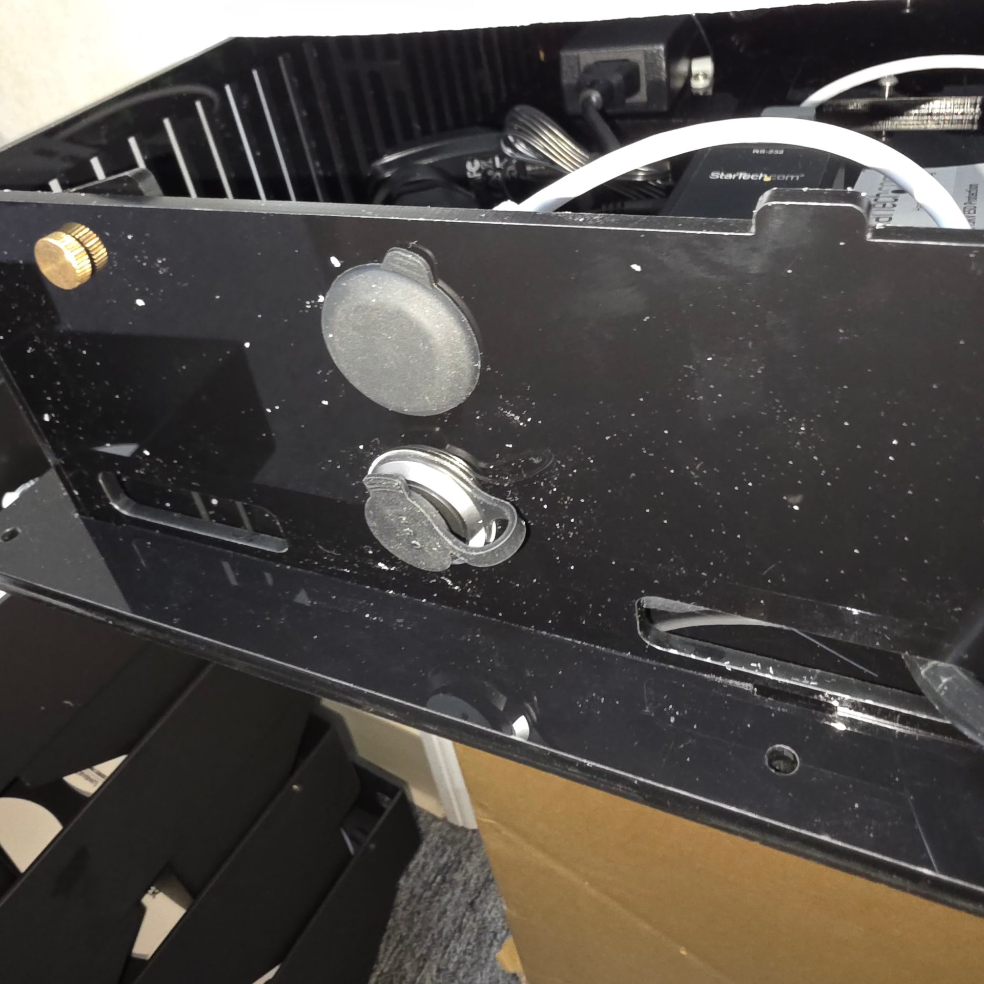
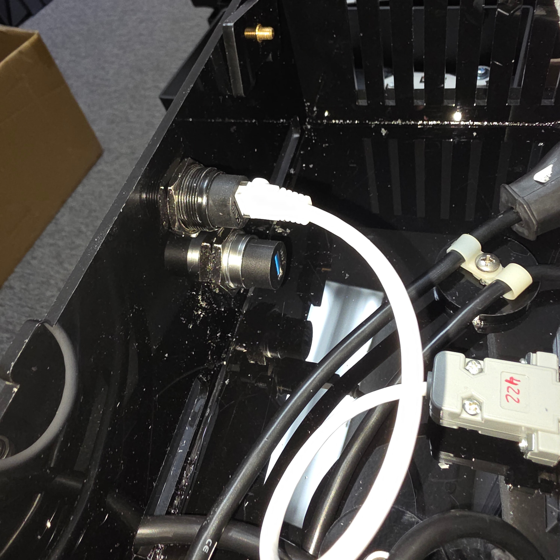
I had to install a couple ports on the side of the case, I would have liked to just plan this and cut a laser hole, but alas, changes dictate I cut by hand,
Now I know acrylic likes to shatter when cutting holes, especially these 1" holes…
Did a bit of digging and found that the common step drill is a good way to cut acrylic holes..
Ok so I give it a try… starting out slow speed and cutting thru 5mm started out very well
but it actually got better as I turned up the speed… amazing…
I cut both holes in a matter of minutes and with no chipping, melting, or breaking…
So now I have an excellent after need for cutting larger holes when needed…
Turns out the cutting angle in the step drill blade is a good angle for shaving off acrylic layers..
I would not have thought of this offhand as a good method…
but a quick google search was the saving grace..
Happy 4th To ALL !
ETHERNET PANEL PORT AND USB PANEL PORT
3 Likes
My Harbor Freight ones only go to about half of this. Amazon Primed a 5-piece set just now, up to 1-3/8". 
1 Like
great buy, you will like them…
1 Like
I use mine a lot. But I had to break out the hole saws (which aggravate me) for some projects. Glad you mentioned this!
1 Like
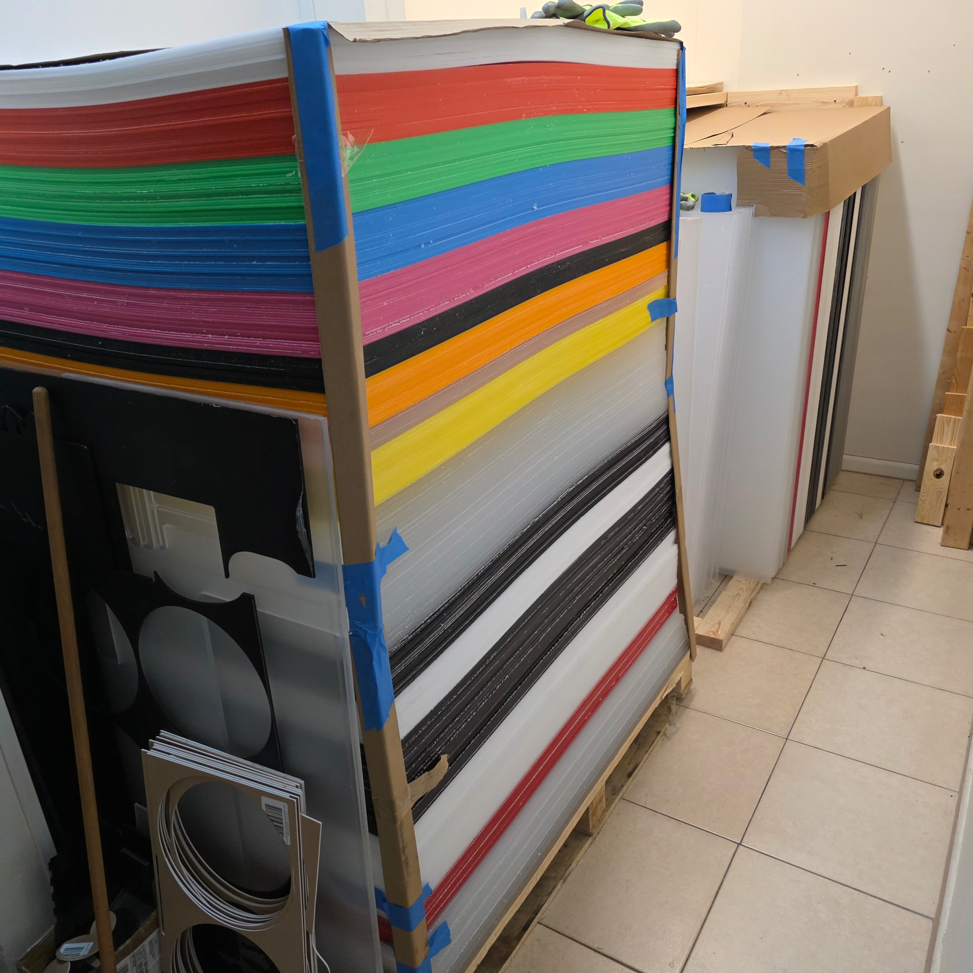
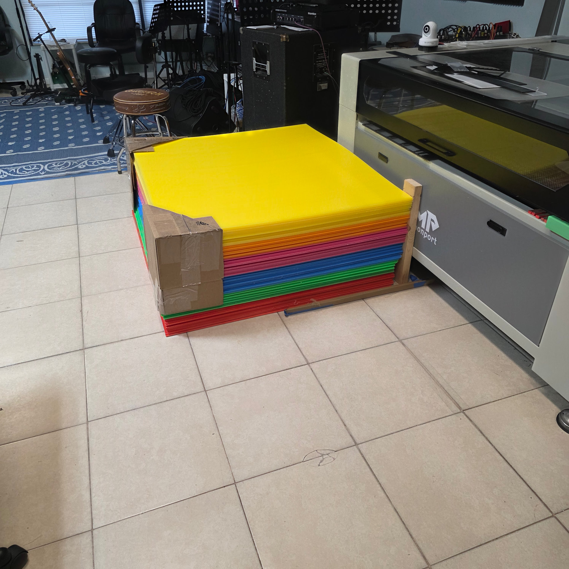
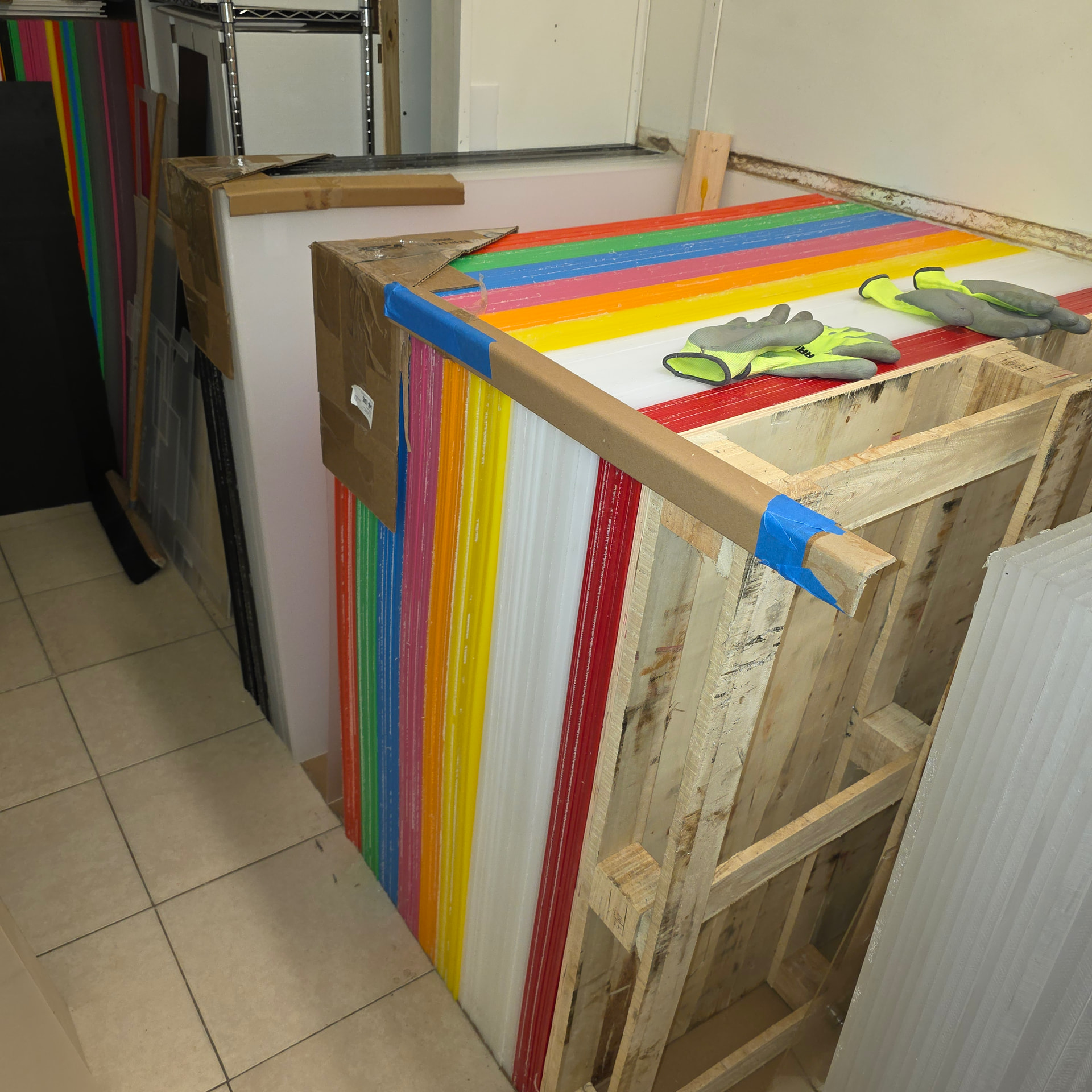
Had a bit of a task to do last week…;.
needed to get at my clear and white acrylic sheets that were stacked up,
but first needed to re-arrange… ugh
this meant moving all the verticle sheets to the other room next to the laser temporarily
then move them back arranged on their sides so I can easily get at them when I needed a particular sheet…
this took me about 4 days of slow moving, it was about 1500lbs of acrylic, and at my age
I tended to be careful and go slow…
did one color at a time… took a break then did a little more. gloves are a must…
one sheet did get away from me and bop me on my big toe… 
all worked out well,… but it was a lot of work…
Been taking Immuno 150 for the past month to get some extra vitamins etc a side
benefit is I have no more aches and pains, even after I play drums in our jam sessions for 2 hrs,
I dont get sore, and most important… the leg cramps are gone…
So getting older is getting better
I have more color sheets than I need, may try to sell a few local thin out the storage area…
as you can see I put cardboard edges on the acrylic, to cover the sharp edges…
easily cuts an elbow or leg…
3 Likes
Well done Chuck, that’s not an easy job for anyone. Why aren’t we fitted with grease-nipples! My Dad knew a special air services guy in Glasgow who applied Wd40 straight outta the can…it’s Organic!!
2 Likes
OMG I had a old friend that used it on his knees… hahahaha
2 Likes
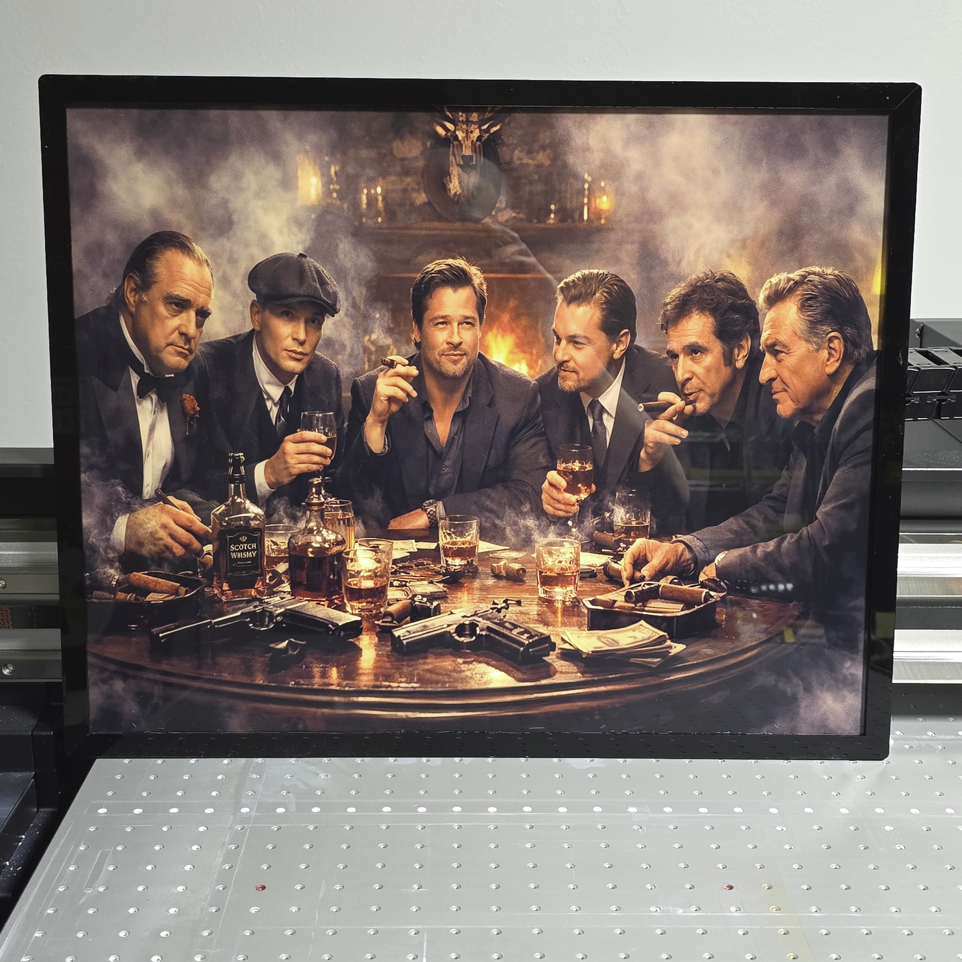
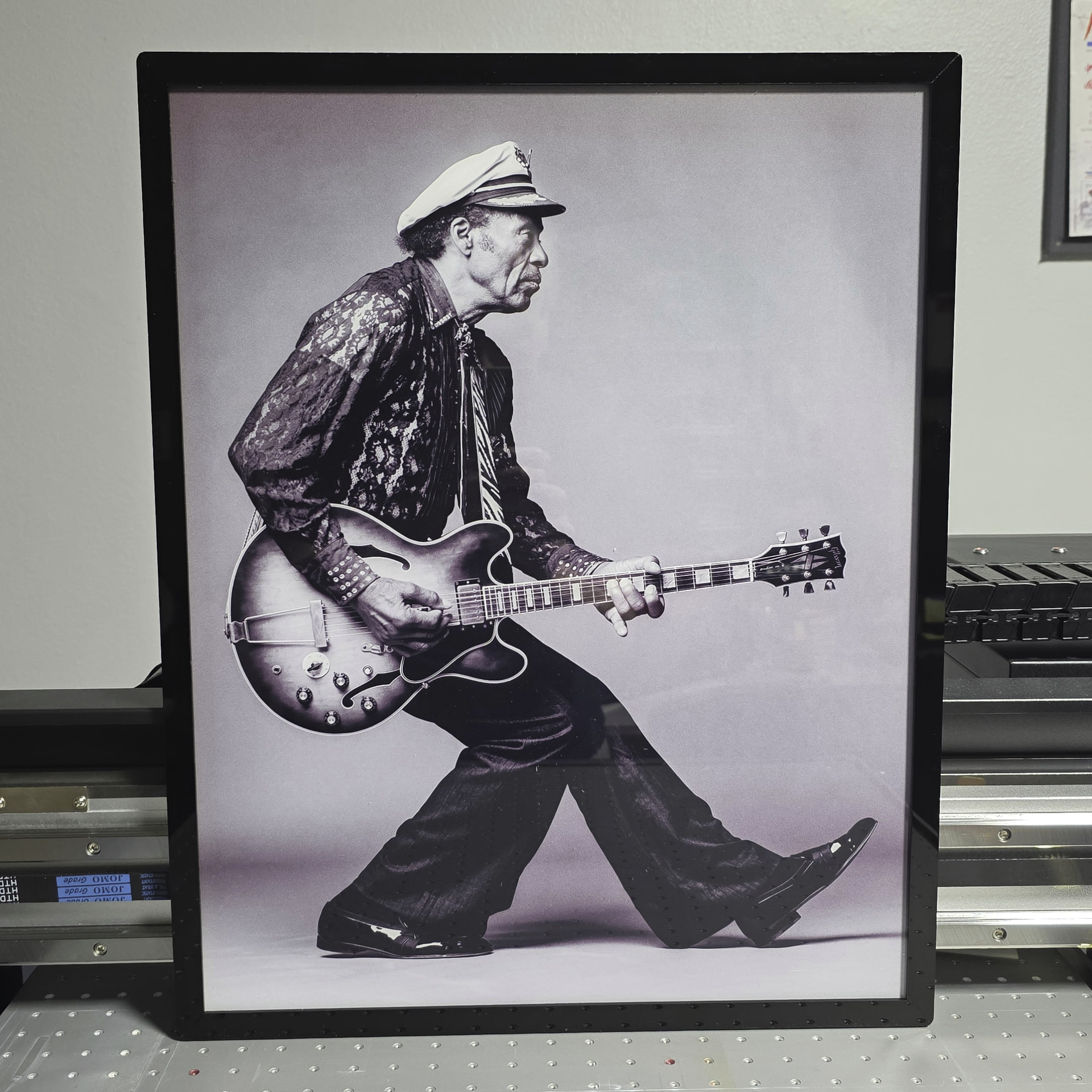
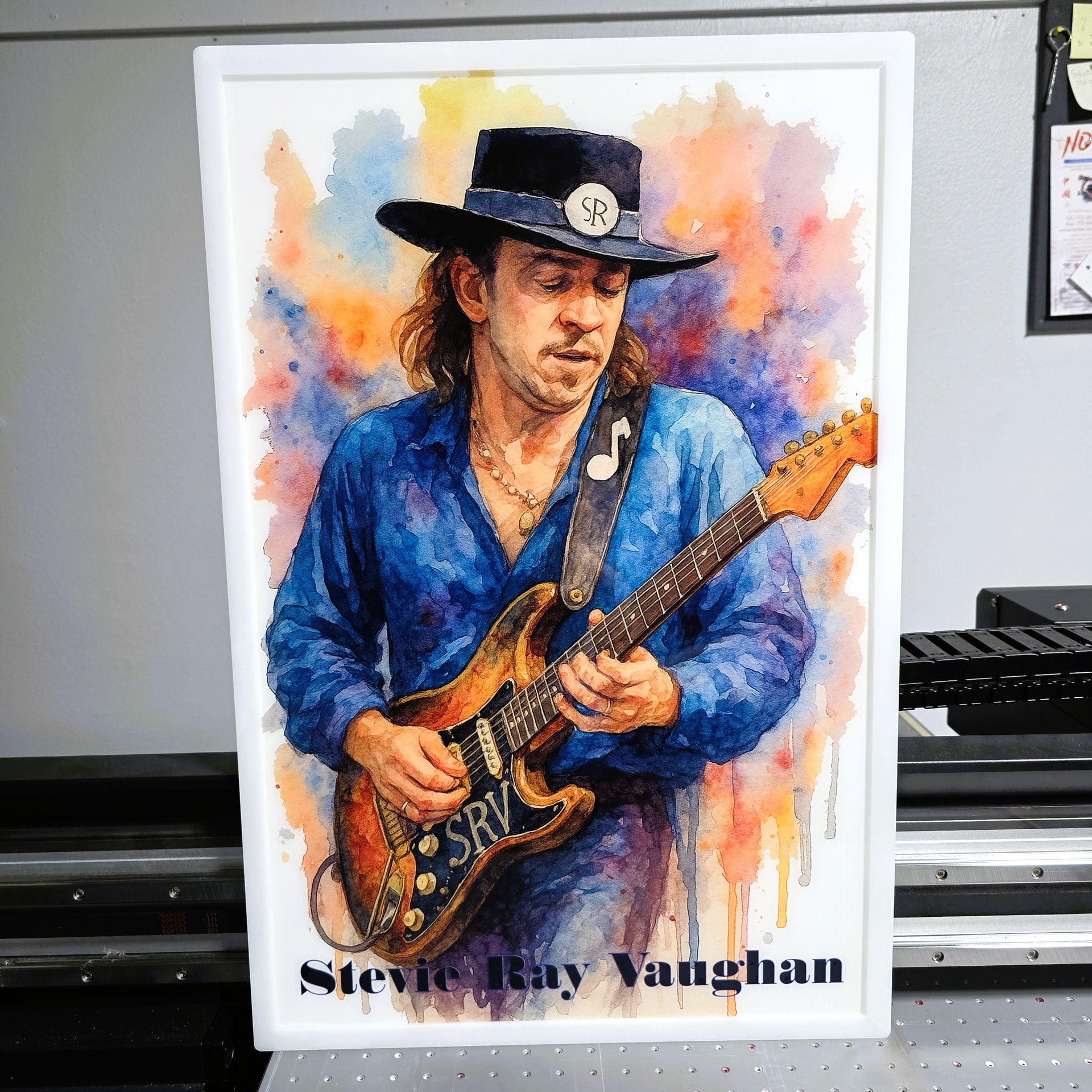
Chuck, Is that picture screaming for a black frame?
Great minds… I initially put a black frame on this and it looked cartoonish…
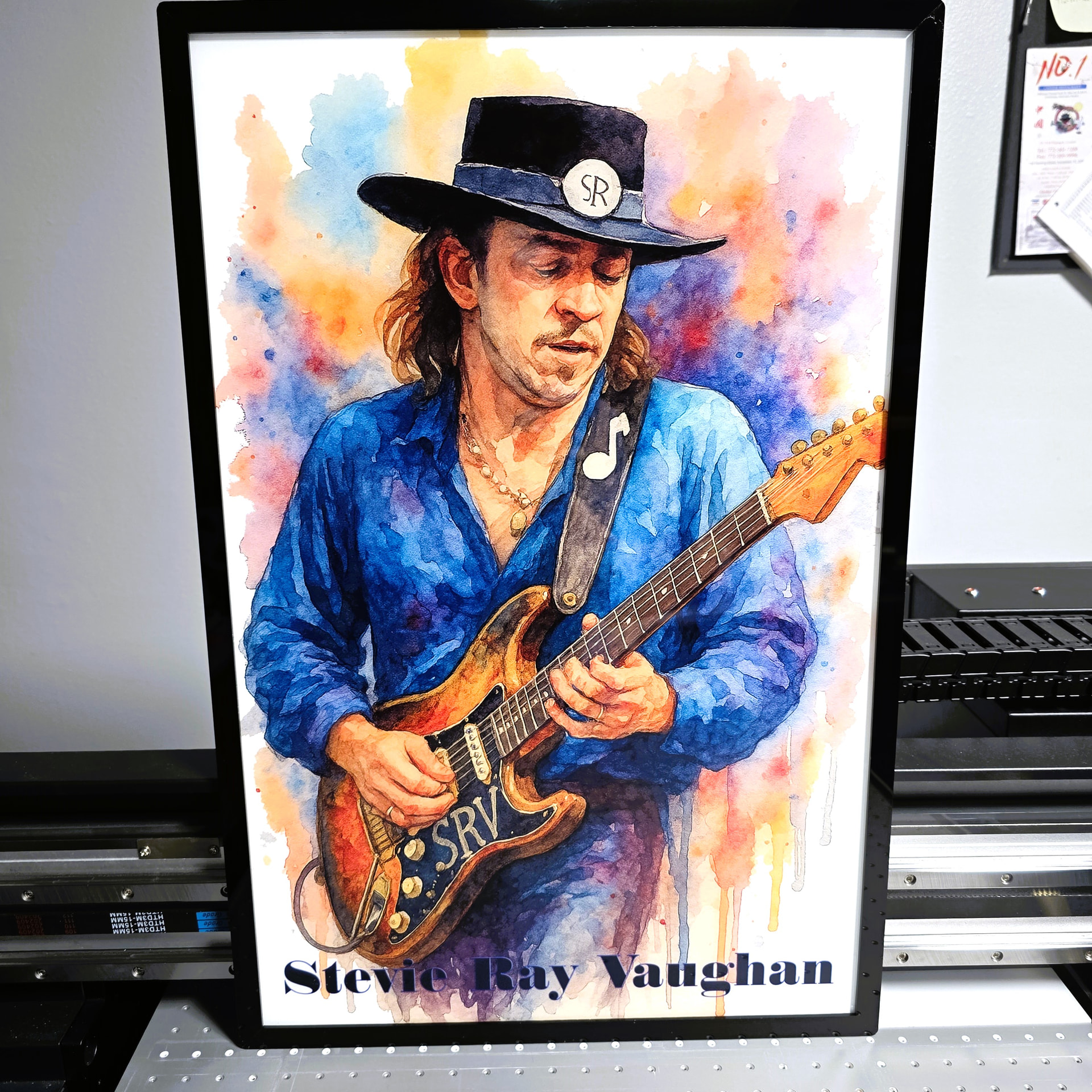
I’ll make one with Black and post it…I am only one opinion
UPDATED: Black Frame SRV ( Looks Great .. Thanks Pete ! )
2 Likes
Been a while…our business is keeping me busy…
But…did find time to set my mirrors, and update some of the Red Dot Laser items…
I made a target holder for my mirrors, it just pushes into the 25mm hole and fits snug with the taper…
it works for mirror 1 and 2
I also made some drop in target tags 2mm basswood.. one side with bullseye the other side is blank..
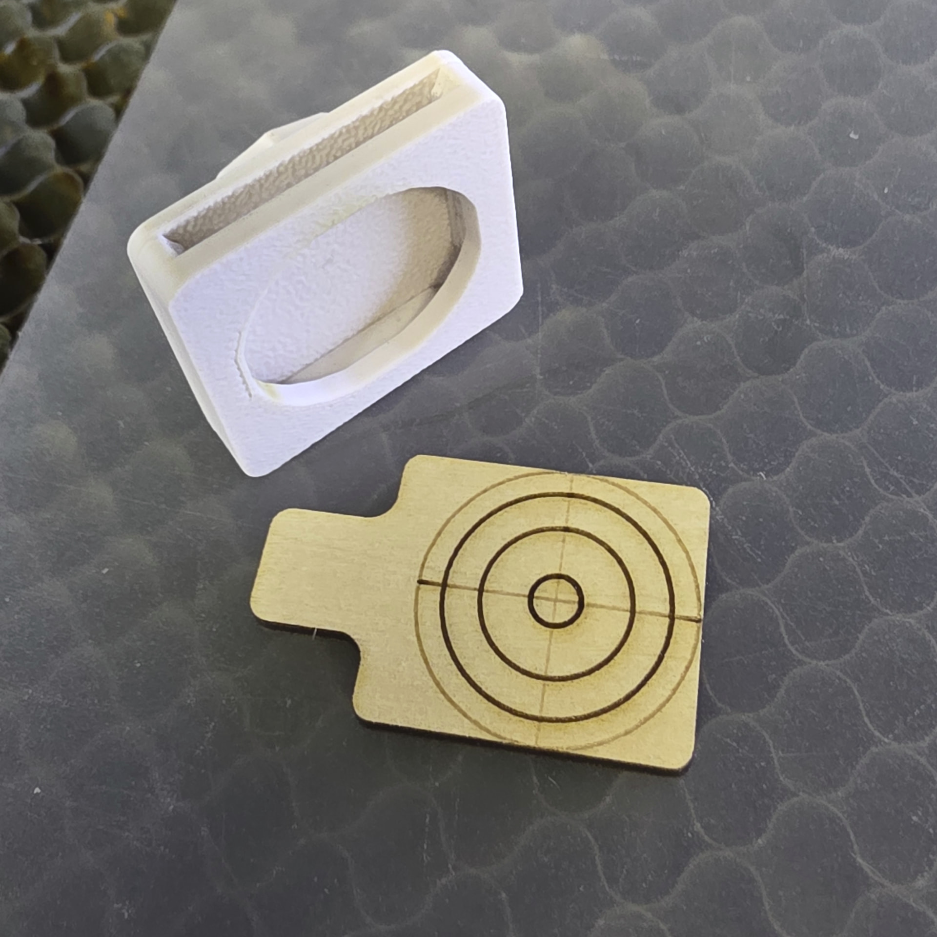
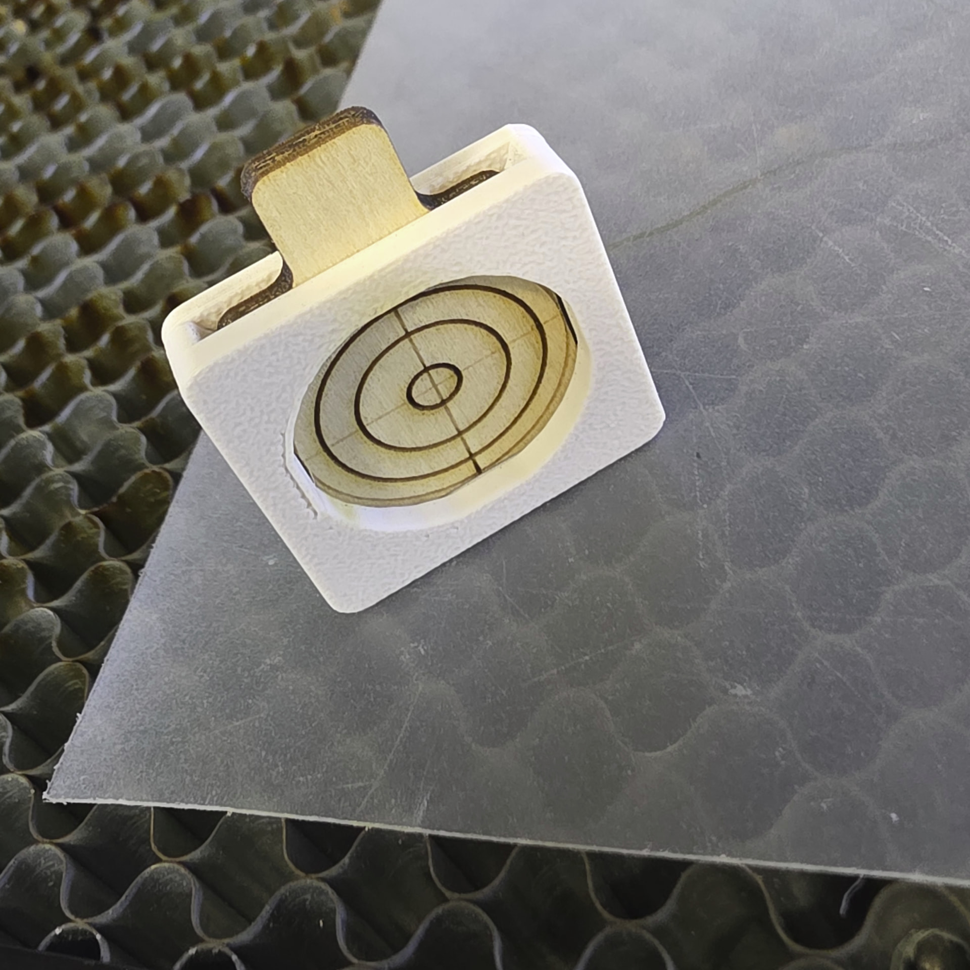
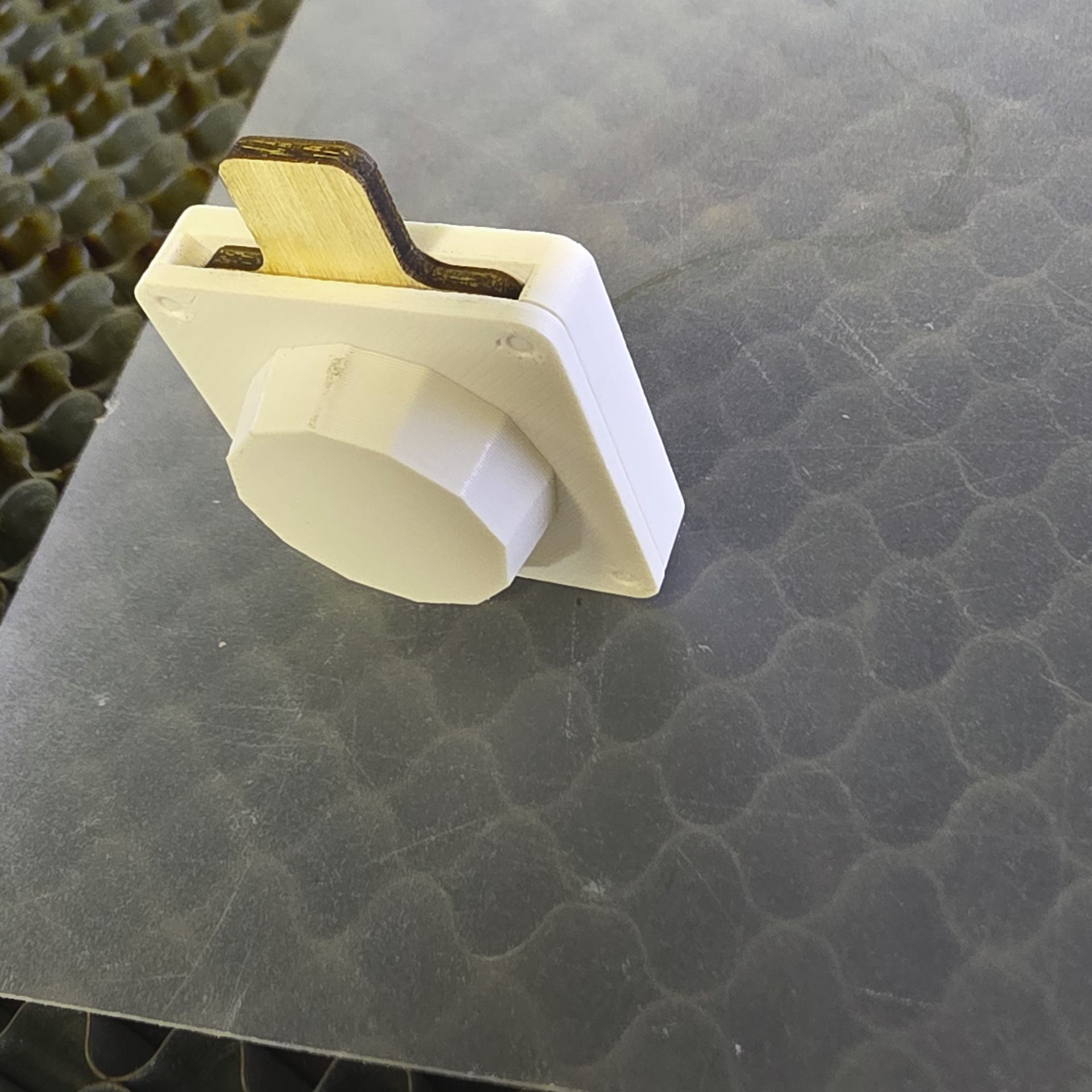
I have the same type for mirror 3 but with a longer push in stem…
Next: I’ve been re-watching Russ’s videos on mirror alignment and there are a few others
that actually cover the same type of aligment process, some are pretty good and mention a few
things that others don’t… so I decided to tackle the entire process…
Checked gantry Square.. good
then pushed the X rail to the back and measured the distance to the X frame to the back wall..
left side was 23mm, right side was 26mm so the X was not parallel with the chassis frame
I needed this to ensure the laser tube on the back side was parallel to the X axis…
after some work I managed to get the Tube square and level with the x axis.
this was a bit of a task…but it is now locked in…
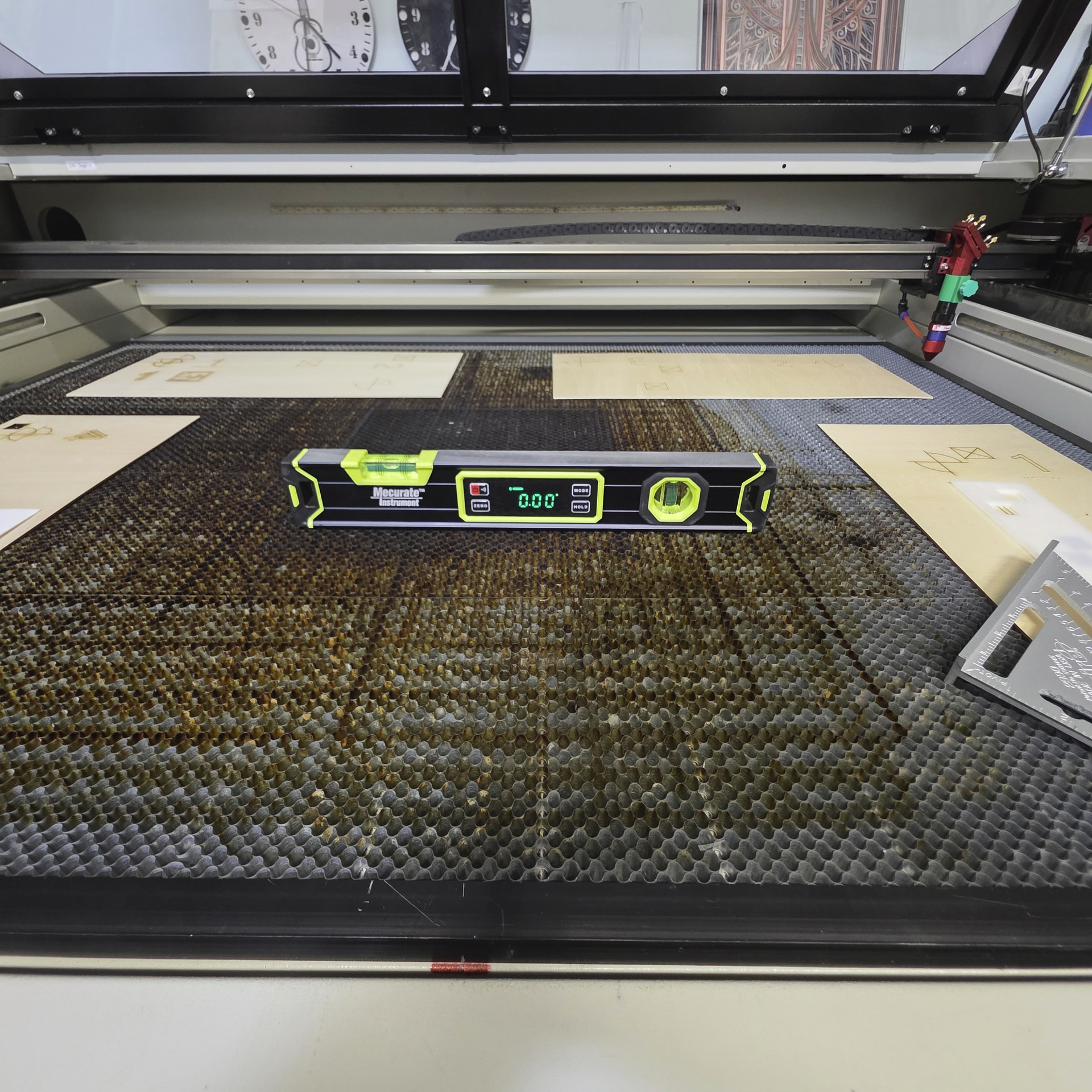
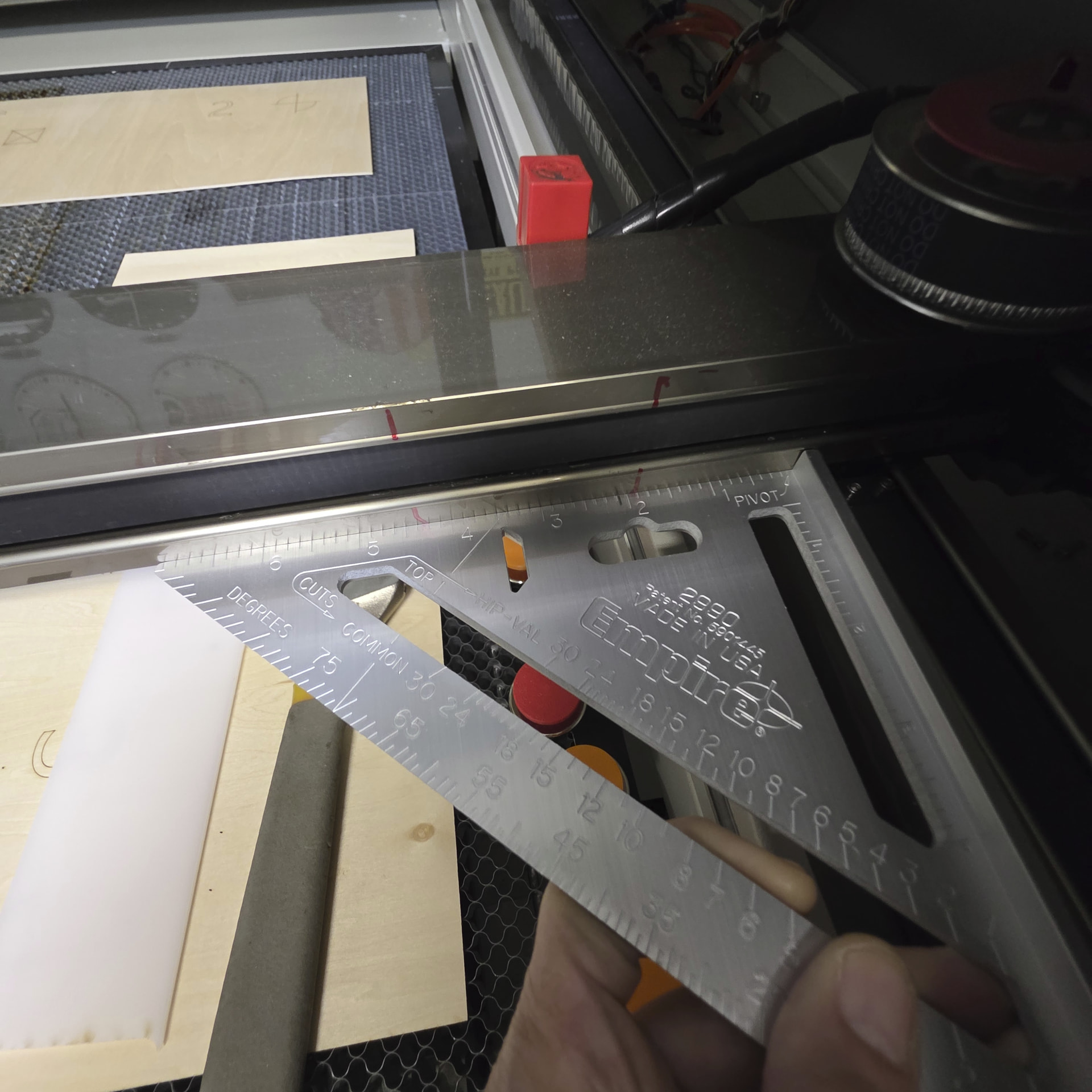

I now followed Russ’ alignment process an it was easy but did not work…ugh…
He did not mention one thing that I felt was important, (maybe not, but it helped)
that is when setting up M2, adjusting M1 process…
the goal is to get the Near and Far burns on top of each other, ignore the center point right now…
and also the process needs to be repeated a few time as each setting changes the Near
but finally the process will reap the rewards and get the Near and Far burns on top of each other…
and if the gantry is ok the target will be close to center.
if not… you need to move M1 mechanism (not the mirror) to align onto M2. Get that and you are GOLDEN!
Next, which I liked, was to to the Near for Far Burns ONTO M3 at the back of the machine closest to the
Laser tube and M1…
Rinse and Repeat the same process as M2, but using M2 mirror screw tuning to get the Near and FAR target on M3 to overlay… …
Next check Far burn M3 back right corner to Far burn M3 front right corner…
and now using M1, adjust (very little) to get the burns over lay… done…
After doing this I check a burn on M3, all four corners and was happy to see that it was only about .5mm
off on one corner…
I know if I went thru the process again, it could probably be spot on…but time did not allow me…
Next task was to get the Burn centered on M3 this would be the Mechanical movement of M2 Front to back
and M3 Up and down…
to achieve this, another item I desperately needed was a locked in method to move M2 and M3 after
loosening the holding screw to slide the mirrors and keep them square so I made some 3D printed
parts to capture the mirror and laser head allowing me to slide and lock easily…
M2 left and right… M3 Up and Down…
Now I was able to get the burn mark centered on the M3 as needed…
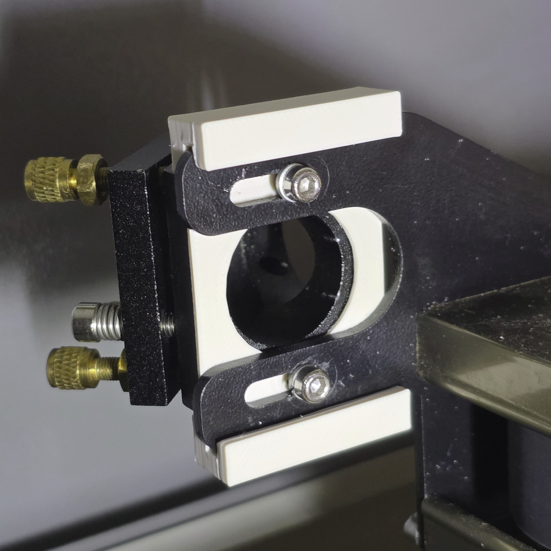
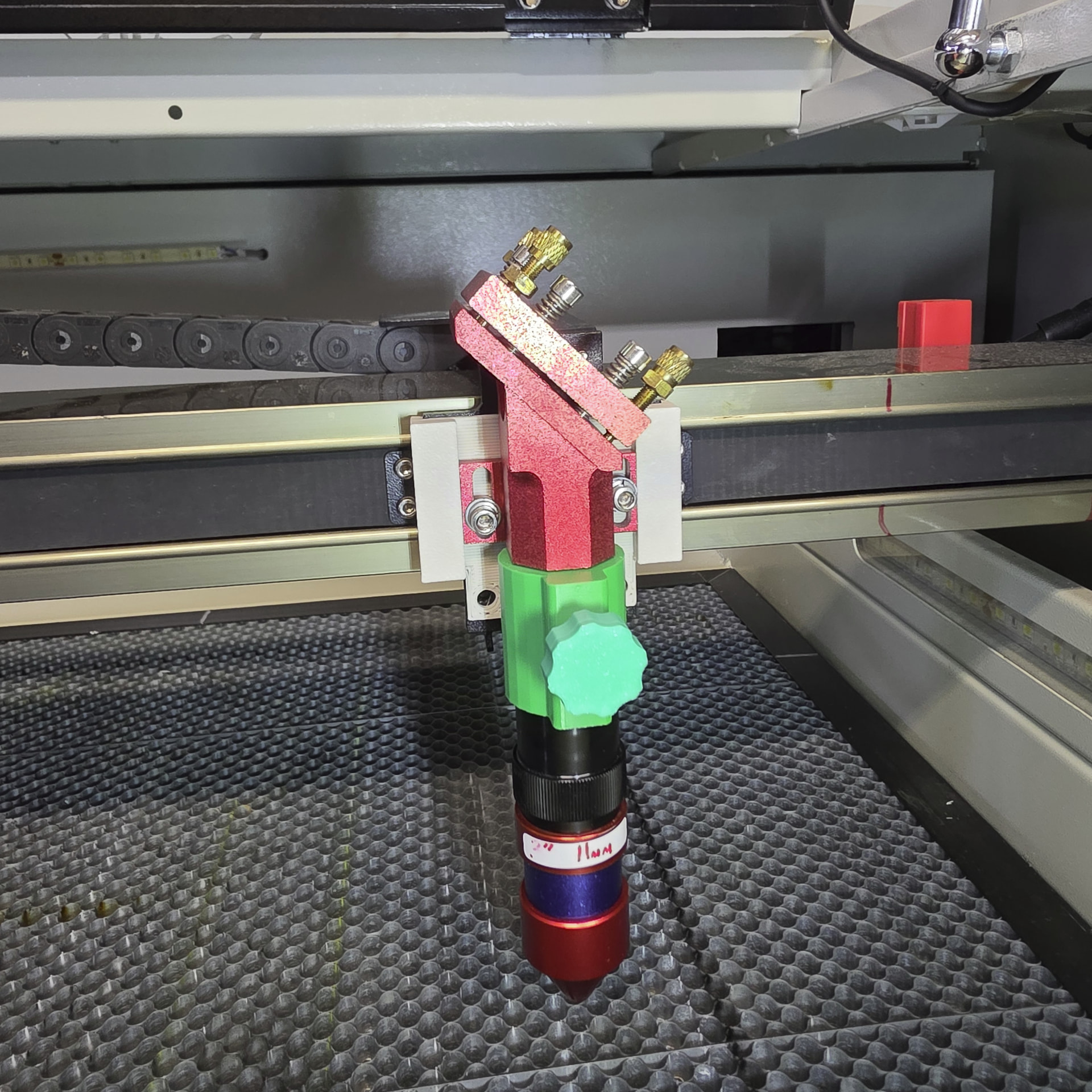
Made sure the Laser tube was vertical, a small adjustment and,
Centered the burn dot with the M3 mirror and this task was done…
Lastly I need to fix my Laser Red Dot…
i have the Yongli Red Dot unit that has 3 set screws for adjustment, most likely done by some
sadist on the design team that hates life…
I re-imagined how to make it better and simply took a page from a Typical Mirror adjustment screw setup
and make 3D printed parts to allow a nice adjustment platform…
I also used a Green Laser dot 12mm unit for the final DOT indicator..
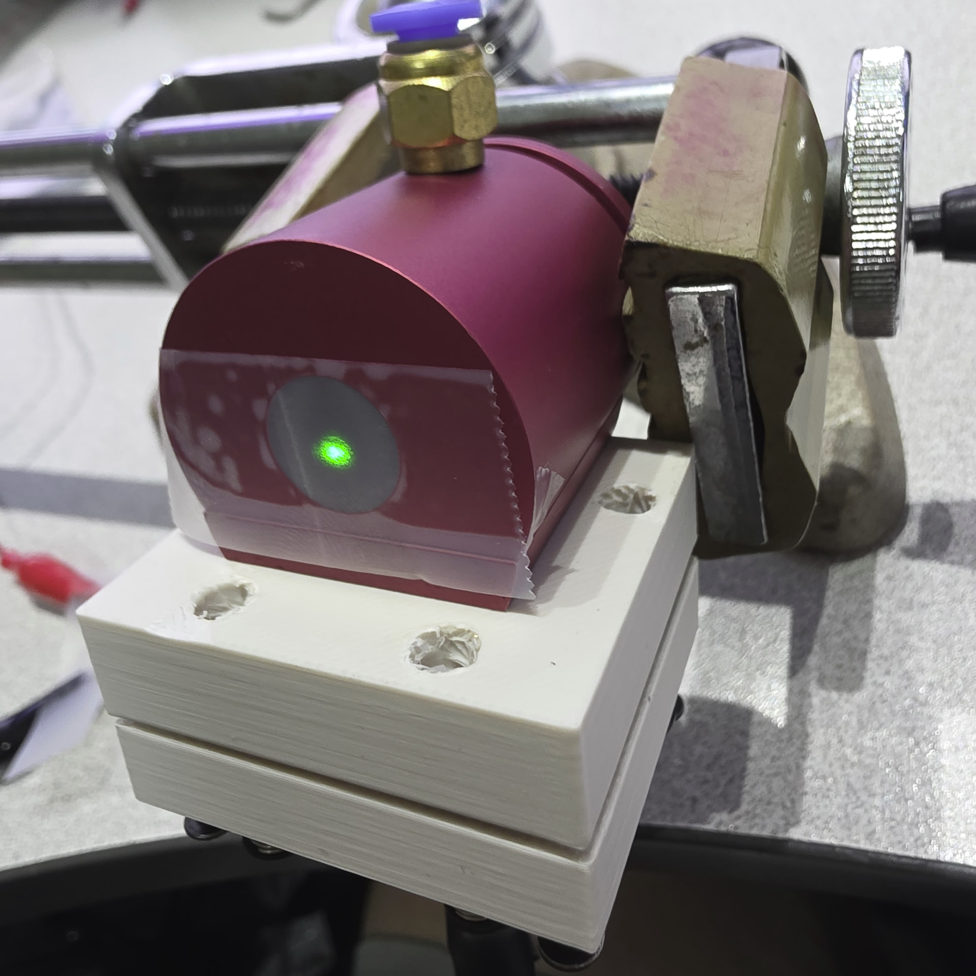
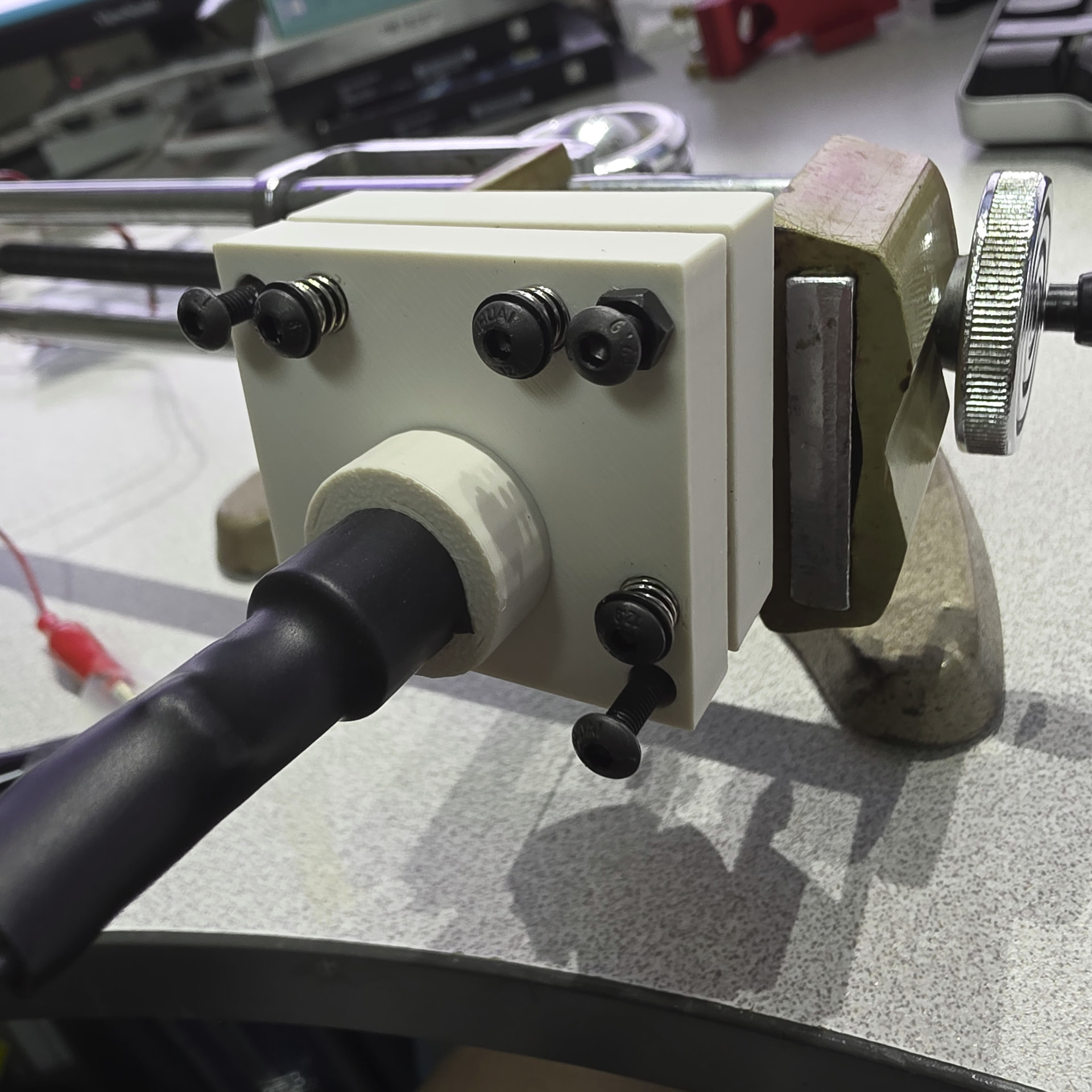
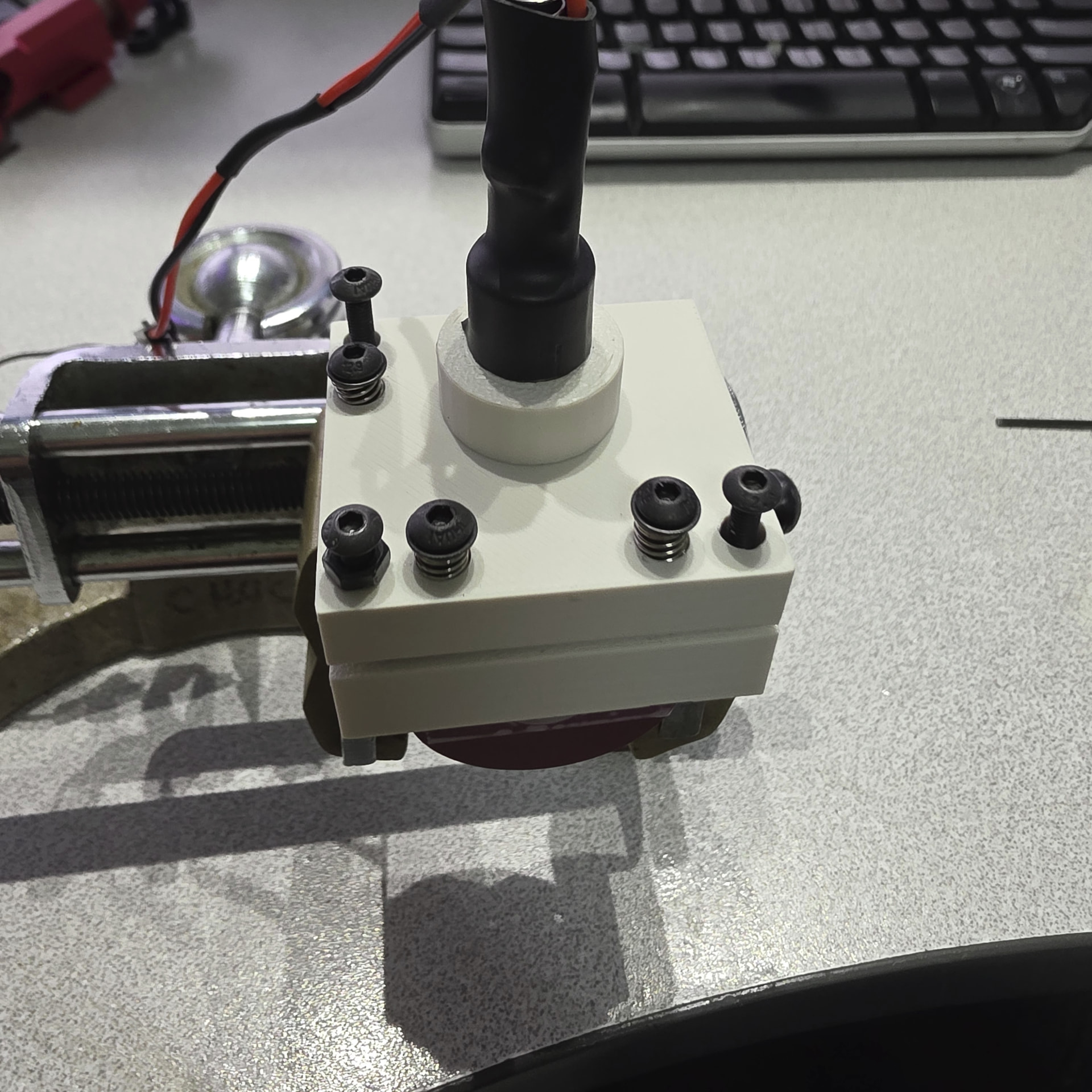
Installed, with easy top adjustment…
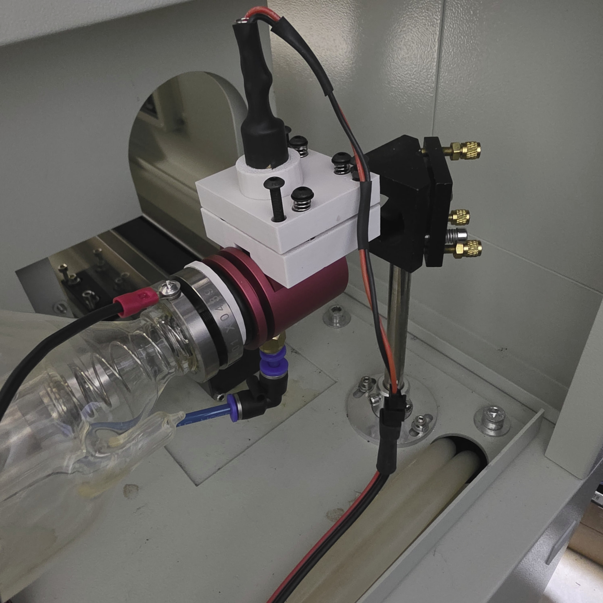
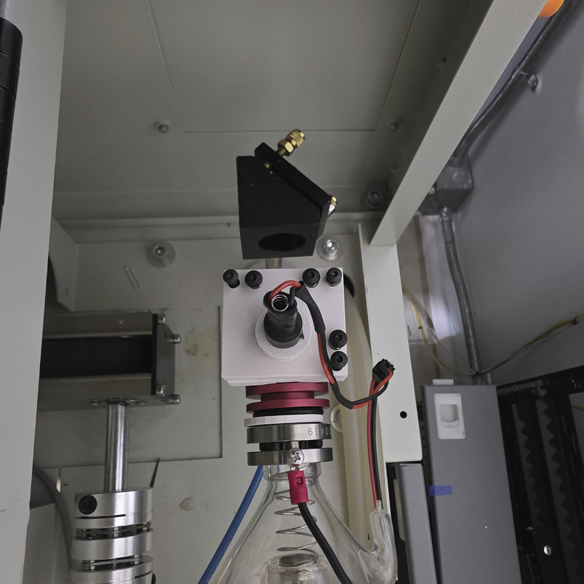
I was able to get the green DOT to actually disappear in the BURN Hole with a 3" lens at 11mm FP
and after moving the head down 15mm it was still vertical and dead center..
Ok this was about 5 days of on/off work and parts design and making…
but I think for now the Laser is good to go…
did some cutting this Morning and, well it was good !
Maybe there are some interesting items here for the folks and I’m sure lot’s of redundancy as well…
but I find it is a good feeling to ‘play’ with the laser and get it tuned up ever so often…
Until next week… see what I can come up with …
Chuck
4 Likes
Laser mirrors absorb a few percent of the incident power, so the 130 W (IIRC) laser can dump a few watts into each mirror. This doesn’t matter with a metal mount, but plastic is a pretty good insulator and the mirror will heat up. Whether the surrounding plastic will deform enough to matter depends on handwaving, but it’s something to keep in mind.
I like the red green dot combiner!
1 Like
the mirrors are in the original metal housing, I just made the guide between the side forks and the mirror metal housing 
but good info…
Thought I’d share today’s experience…
decided to do a re-align of the mirrors this morning, was not happy with M2 3D printed guide…
after tightening down the screws the plastic compressed and changed the position.
I thought being .75mm thick it would not be an issue… but…
Note to self: 3D printed items can’t be a quick fix for everything .
Anyway, the re-align went great… and I decided to cut some 10mm acrylic in the front
right corner (furthest laser point).
My original setting for 10mm were 2mm/s at 50% pwr 5psi air.
so after playing around I was able to cut the 10mm cleanly with 2mm/s 38%pwr 5psi
when I used the original setting the part (a test square 12 x 12mm) would not fall out cleanly.
after I changed to 38%pwr the part fell out cleanly…
What I hadn’t realized was that the excess power was causing too much of the acrylic to melt
and reform behind the cut, re-attaching the part…
That was a very nice find, I had never read too much about excess pwr cutting acrylic, or I may
have missed it.. but it was a nice discovery none-the-less…
and having the right front of the bed able to cut now makes the entire laser bed 1300x900
a usable platform…
anyway just a thought ‘out loud’…
chuck
1 Like
For 6-ish mm acrylic, I do a two-pass cut for that very reason:
- The first pass gets mostly through: 10 mm/s 60% of 60 W
- The second pass makes clean edges: 30 mm/s 60%
Both with about 12 l/min air flow, which is about as much as my piddly little pump and plumbing can handle.
Similar logic applies for thicker acrylic, which I cut as rarely as possible. 
1 Like
I’ll give that a try, it may be quicker to do a two pass 
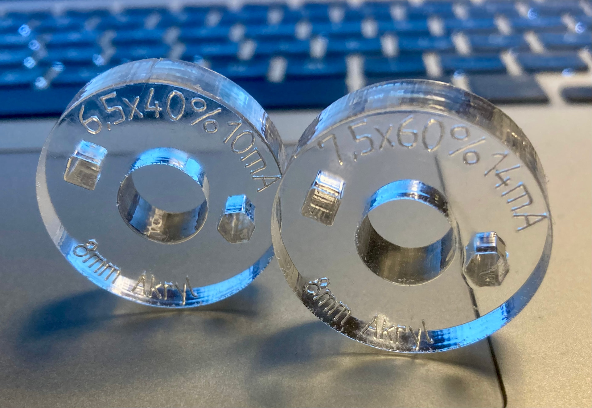
The speed/power ratio when working with thicker acrylic is a bit strange. To avoid fusion after cutting I always try to run as fast as possible. In an older example of 8mm acrylic testing, it is seen that by reducing speed by just 1 mm/s, from 7.5mm/s to 6.5mm/s, power can be reduced from 60% to 40% (14mA to 10mA) with similar quality.
But for 6mm which I often cut, my settings are 6mm/s at 32% (8mA) power. The air flow is what my 2 pumps give together ca.25 l/m, which is not very much.
1 Like