Come to think of it, unless you’ve dramatically reduced the controller’s Start Speed, running at 2 mm/s may be throttling the power to-or-below the Min power setting:
Who say’s old dogs can’t learn new tricks…
Very good info…
Not that I NEEDED an excuse to cut acrylic… but I will be…
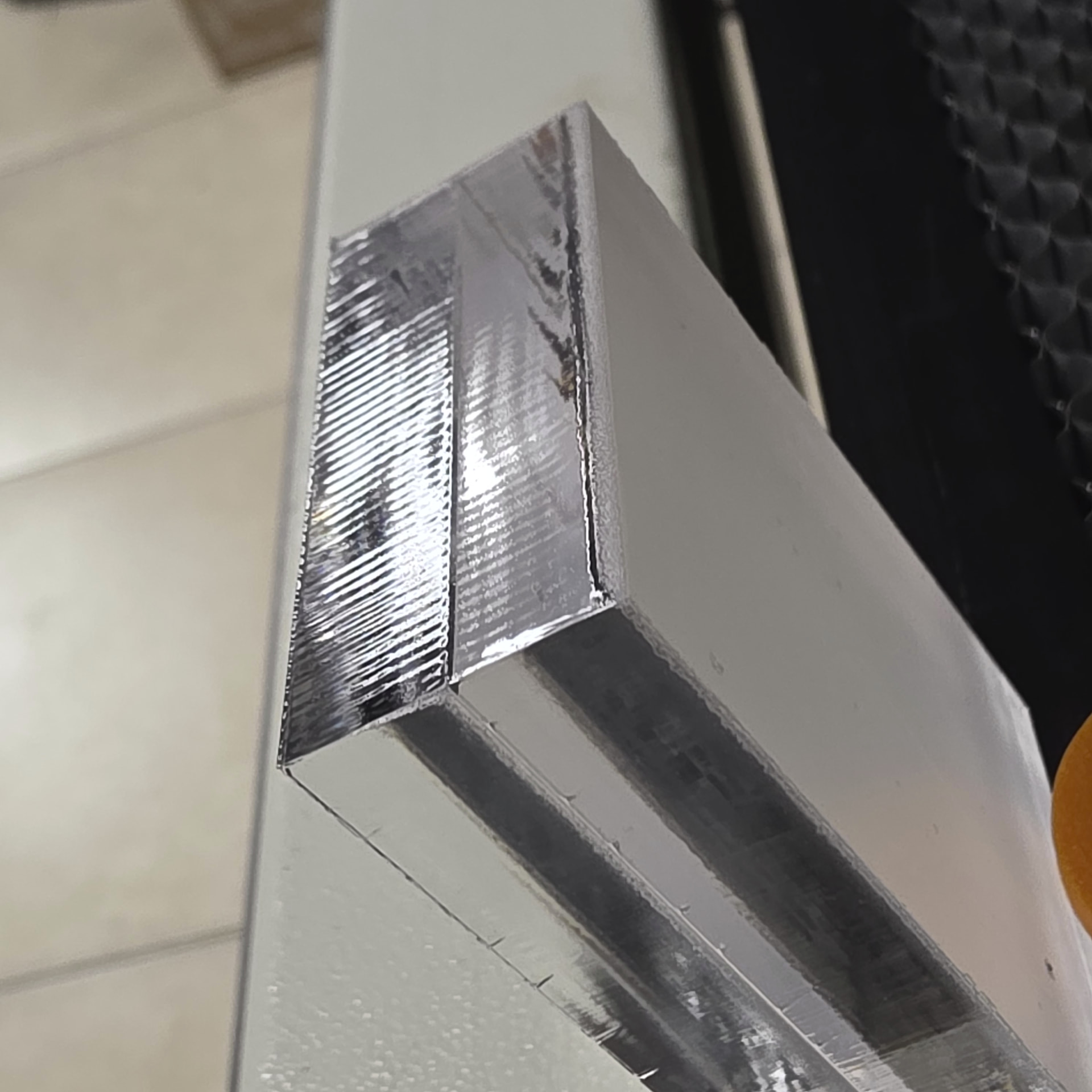
10mm 130w laser 2mm/s 38% power FP set to top of material (not inset)
1 pass..
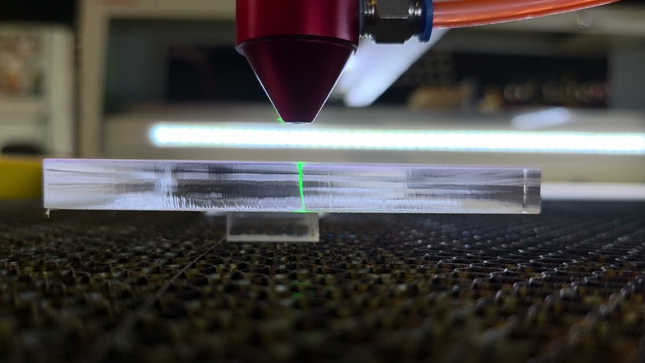
That’s a neat shot! ![]()
Just tried this for fun .. I was surprised !
Acrylic Cut 20mm thick two 10mm pcs stacked
.75mm/s 75% power 28ma (130w tube) 5psi Air 1mm FP inset to material
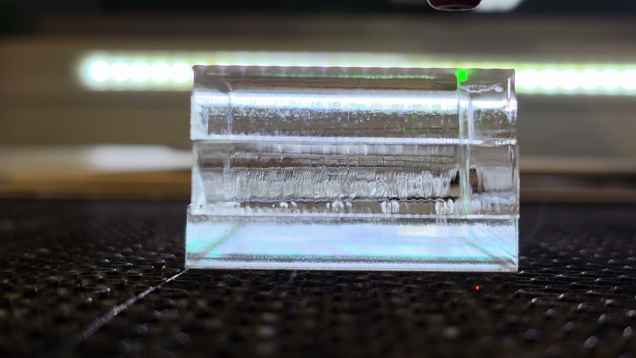
this is the finish
Those videos clearly show the “beam dragging” effect: the bottom part of the cut happens well behind the beam position, due to the acrylic not vaporizing instantly and the gases doing the cutting.
An earlier discussion pointing to a Sadler video:
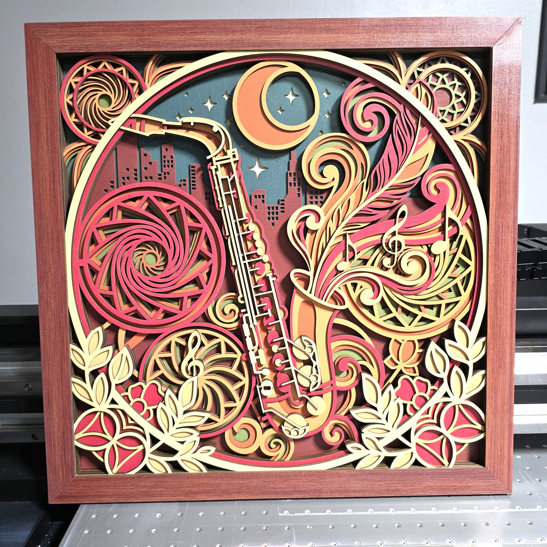
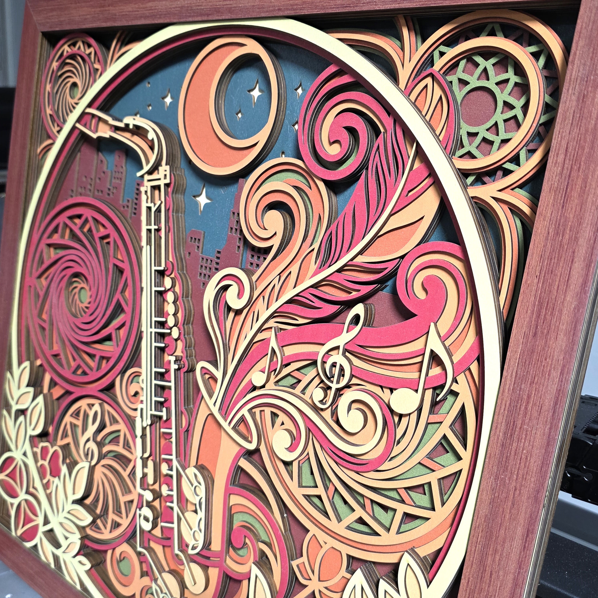
Great detail even at Big size.
Talking about the frame, right?
What frame! Oh yeah, I was too zoomed in looking at the detail…Great frame..totally fabulous.
Ed…
are you referring to settings in the RUIDA MENUS ?
can setting the START speed to say.. 1mm/s
not sure where to look for these settings… RUIDA MENU / light burn menu settings ?
It’s accessed through the LightBurn Machine Settings window. The Start Speed you want is in the Cut Parameters section (or something similar), with defaults around 10 to 15 mm/s; there are others for the X and Y axes in the Engraving Parameters section that (probably) don’t apply to cutting.
What those speed settings do, in any detail, remains a mystery. ![]()
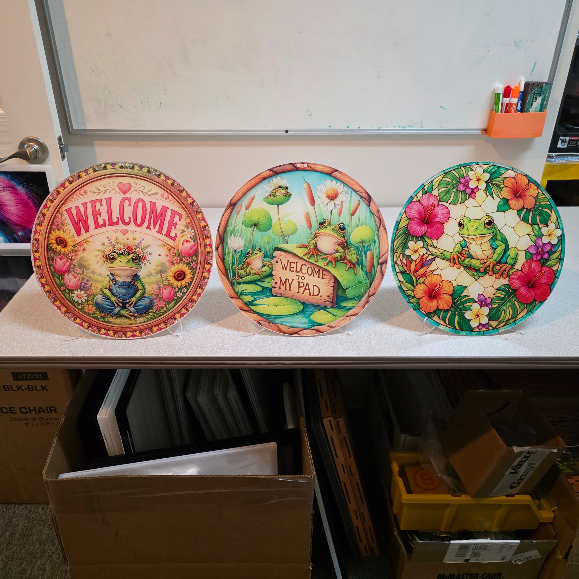
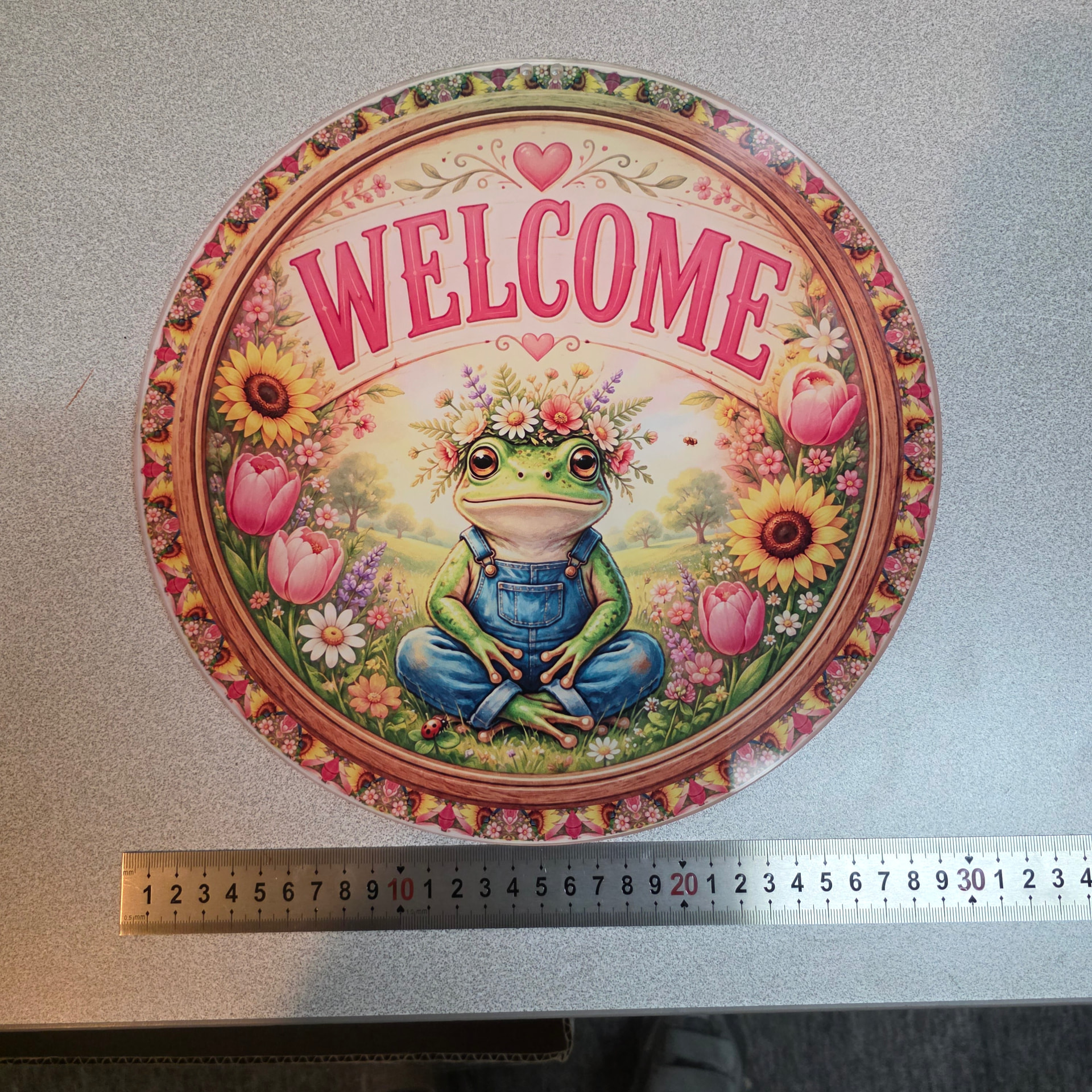
WIFE LIKES FROGS 302mm round 5mm acrylic with stand UV Reverse PRINTED
two small holes on top for leather hanging string loop
What is reverse printing chuck, and why!
REVERSE printing is when the picture you are printing is on the back side of material
ie. acrylic, so the picture needs to be reversed so when printed on the back side it shows correctly
for viewing from the front… and putting the ink down, usually a layer of white base is printed then the color on top…
but for reverse printing, the color goes down first so it can show thru, and then the white base is put on last…
so when the acrylic is turned over and the picture is viewed thru the acrylic you see the colors and the white backing provides a filler and back layer…
clear as mud ![]()
Update: Picture:
First layer is the color, then followed by the White backing..
Should be very popular as they look great.
Thanks for the explanation…that method makes a lot of sense.
Quick Note todays activity…
I get into the office around 4am to cut some 302mm round 5mm ‘welcome plaque blanks’
and grab 3 sheets of acrylic… ready to go.. ![]()
Set up the typical speed and pwr settings… CUT…
as I watch the cuts being made I see the green dot laser (thru the mirrors) seems to be dimming…
hmmm I was thinking the green dot laser was over heating and dimming… but I have a potentiometer installed and it was set to mid low intensity, maybe 12ma run current… should be cool…
I open the back panel to look at the laser tube and, with cutting finished and laser off, I put my finger over the IN side of MIRROR 1… just to see if the green dot is basically centered and maybe dimmed…
yup it was centered, and BRIGHT… hmmmmm
also I rested my finger on the aluminum mirror 1 mount and it was HOT!!!
CRAP… is the laser beam hitting the edge ? I grab a piece of tape and do a PULSE SHOT
DEAD CENTER… !
ok what the heck is going on now… seems the mirror is heating up?
I replaced all three mirrors 6 months ago with American Photonics mirrors..
AND I remembered Lou ( inside tech guy ) had mentioned he replaces his mirrors every 6 mos..
Now I do have a 130w laser and recently did run some power tests pushing the current up to 30ma
to get around 110watts, just for testing..
So i take the M1 mirror out and it was very worn , not sure if burned is the right description…
but the coating was extremely scarred…or gone…
I replace M1 with a new mirror, (keep a few on hand always) and the cutting was back up to par and the heating was back to … cool, after cutting 2 sheets at 50watts run power…
Lessons learned, I never thought that M1 would be taking the brunt of the laser tube output
even tho it was obvious after thinking about it..
As long as the cutting seems normal, the wear on the mirrors, does not come to mind…
but it will now…
thank goodness the green led dimming offered an indicator that an issue was at hand…
I’ve put on my calendar 6mos replace cycle to keep the mirrors running optimum..
This was one of those good days that things went wrong for all the right reasons and the solution was an insight to keep the future laser operation in tact !
It made perfect sense that the M1 aluminum mount had gotten hot, as aluminum is a good heat sink, but was glad to realize that all that laser power was being collected at the nearest 1st point of beam travel… so… now keeping the obvious at hand…
I may see a future temperature display with remote sensor tacked to the M1 mount and in viewing
range to monitor any abnormal temp rises…
since I do run some wattage into M1..
Sweet… another project… ![]()