New to lasers and am having an issue with a hand-me-down machine. It has a GRBL 0.9 J+ controller and a 15 Watt blue diode. Whether I’m using Lightburn or LaserGRBL, The Y axis will only go in one direction. If I reverse the 2Y axis wires and choose a direction it’s it just goes in the opposite direction so it seems to me that it’s either a wiring issue or a command issue. Not sure what to do. Its running GRBL 1.1


Did it ever work correctly while on your bench?
The symptom suggests the DIR signal from the microcontroller isn’t making it to the Y axis stepper drivers, but it may be more complex than that, because the machine appears to have two Y axis drivers for the separate motors.
Try this:
- Turn the power off
- Unplug one of the Y axis motors
- Turn the power on
- Does the machine at least try to move in both directions?
- Does it move properly in response to the jog buttons?
Repeat that with the other motor.
Let us know how it behaves and we can take it from there.
So it’s been upgraded at some point? Did it work after the upgrade while you had it?
I just got it yesterday so this is all it’s done for me. Never had it before it was upgraded. Unplugged both motors and it behaves exactly the same. Only 1 direction
Soooo it sounds like a hardware problem, where the microcontroller’s DIR signal is not reaching the stepper driver.
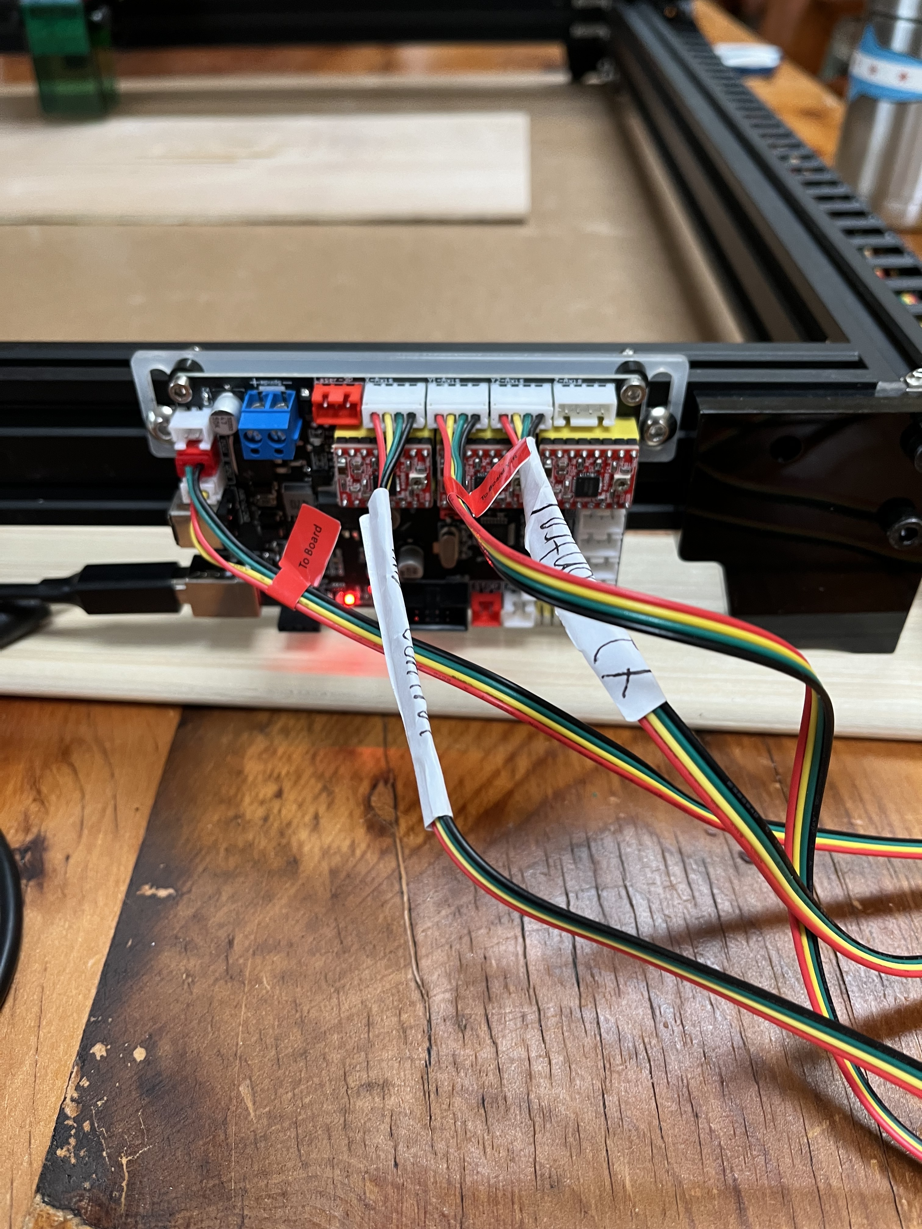
The controller has three small stepper drivers plugged into it. One will be for the X axis (probably the one on the left), but it’s not clear whether the two Y axis motors use separate drivers or share a single driver.
How to find out:
- Turn the power off
- Loosen the Y belts enough to get them off the motors
- Unplug the rightmost stepper driver from the controller
- Turn the power on
- Do both motors turn (even if only in one direction)?
If so, the unplugged driver was for the (unused) Z axis. In that case, you have a spare driver and can swap it for the Y axis driver:
- Turn the power off
- Unplug the middle stepper driver from the controller
- Plug the “spare” driver into that socket
- Turn the power on
- Do both motors turn properly?
![]() CAUTION
CAUTION ![]() : The drivers will not survive being plugged in backwards, so be absolutely sure they are oriented correctly and lined up with the sockets on the controller.
: The drivers will not survive being plugged in backwards, so be absolutely sure they are oriented correctly and lined up with the sockets on the controller.
If one of the motors doesn’t turn after you unplugged the “spare” driver, then the Y axis uses two drivers and more debugging is in order.
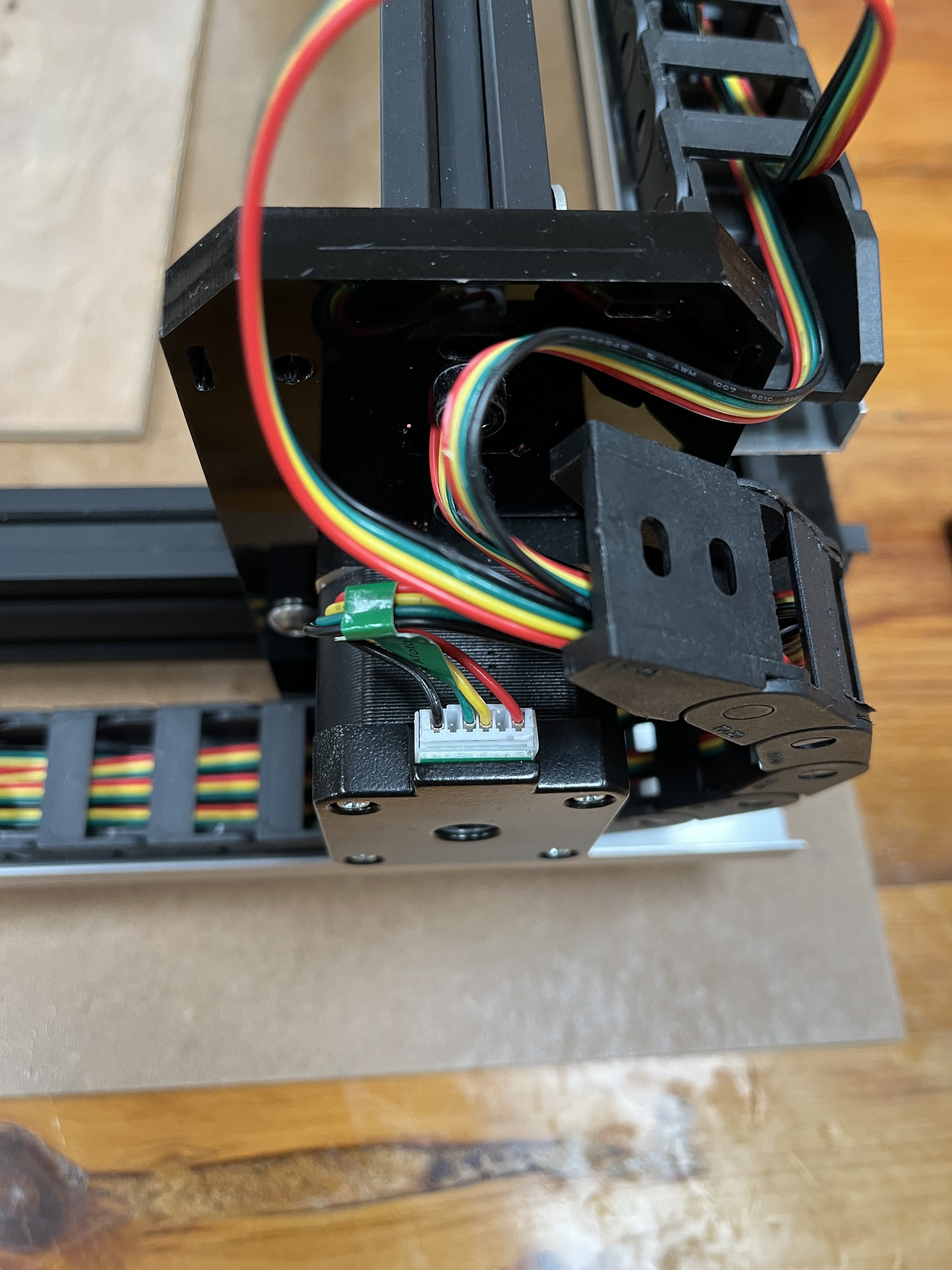
Forgive me for my lack of knowledge, but I just want to be sure I understand. And thanks so much for taking the time to try and help me. Very much appreciated. Also, just to be clear, if I draw a square and ask it to frame it, it will complete the framing, just all the Z motions are towards the front of the machine. Also, I can see in the G code that the code is obviously correct with the positive and negative values. So the signal is getting there and the steppers work, it’s just not the correct direction. And yes, you are correct, the left plug is X and the next is Y1 and then Y2 and the final is Z which is unused. All 4 are clearly labeled. Not sure if that helps. When the framing occurs the gantry moves very smoothly. The only thing holding me up is that one direction.
Also, I can clearly see that both Y motors are individually wired to the controller if that helps
One final bit of info. In laser GRBL, i went into the GRBL controller and tried to invert the Y axis in $2 and it had no effect at all. Motors still worked, but it did not invert the direction
That inverts the DIR signal, which should make it move the other way. That it does not move the other way definitely suggests the stepper driver either isn’t getting the DIR signal at all or is ignoring it due to an internal fault.
So try the controller tests I suggested and see what happens.
It is possible the microcontroller output is dead, but try the simple tests first.
So facing the engraver, the way it’s designated, the left motor is Y2 and the right is Y1. On the board, the left 4 wire plug is the X and it works perfectly. The center 2 plugs are supposed to be the parallel Ys. Y1-axis is the first and the 2nd is Y2. With the left belt loosened and Y2 unplugged,only Y1 motor runs. It does the same pattern if I do the reverse for the other motor. Here is where it gets interesting. So if I reverse why one and why two on the board, the Y axis goes the other direction only. Meaning by reversing the two plugs it reverses the direction why travels. Also, I hope I can explain this correctly but if I unplug Y1 from the board and plug Y2 into the Y1 slot, the laser moves the opposite direction only. The reverse is true if I move Y1 over to Y2 it works but only 1 direction, hope that makes sense. Im about ready to just buy a new board.
It’s almost like something in the board is miswired because clearly it can send both positive and negative instructions to the Y axis because reversing them gets me the other direction. So if I wanted to go through the pain of figuring out which pins are responsible for which positive and negative signals, I could probably rewire the plugs and get what I want, but that seems like a ton of work for something that’s not done correctly.
Correct me if I’m wrong about this, but the problem is that the Y axis can move in only one direction. You can change that direction by flipping the wires from the controller to the motor, but it still moves in only one direction.
If that’s the case, then the fault lies between the controller and the stepper driver boards.
That is the expected behavior: the motors turn in opposite directions, because they face the machine in opposite directions.
That will introduce a whole new set of problems, because you must transfer the configuration from the old controller to the new one. Everybody gets that wrong.
Given that you have nothing to lose, try testing the stepper motor driver boards as I described earlier. Go through the whole process, because I’m still not certain the Y axis uses only a single stepper driver.
The G-Code instructions you can read live at a great distance from the electrical signals sent to the stepper motors through the four wires you can see. Correct G-Code is necessary, but not sufficient, to having the laser head move where it’s commanded.
You are correct. And I went thru everything you suggested so far so nothing left to do there. I did both the jog test with each motor unplugged and the 2nd test with the belt loosened. I think the board is misfired or flashed incorrectly or something. Definitely has 2 Y drivers that is confirmed
The fact that both drivers turn their motors in only one direction suggests that the microcontroller output signal is dead, which means you need a new controller board.
At the risk of pushing you out of your comfort zone, you can measure the DIR signal at the stepper driver pin with a multimeter. The pins are labeled on the side of the PCB you can’t see without unplugging them, but that’s the best way to locate the DIR and GND pins.
If the microcontroller output is dead, the voltage on the DIR pin won’t change, regardless of which direction the motor is supposed to move.
Although I (now) doubt it will help, you can replace the stepper drivers:
https://www.amazon.com/s?k=drv8825+stepper+driver
The only adjustment required is turning the tiny trimpot to about the same position on the new boards as on the old ones to set the motor current.
Here is what I don’t understand by switching the wires. I’m getting the opposite direction so clearly the motors are fine and the board can send both signals. So it seems to me that the Y axis is off somehow. Also, it’s a bit confusing as to why when you switch why to into one, it switches the direction.
One other question/comment clearly there are only three drivers on the board, but there are four ports for X, two Ys, and a Z axis. So theoretically, the center driver should be sending the same/identical signals to both Y1 and Y2 correct? So the simple fact that moving Y1 over to Y2 slot reverse the direction of travel tells you something is wrong with the board. If it were correct, it should replicate the error and move only one direction. Ohhhhh wait, maybe you said this and I missed it. But since the motors face each other, each motor receives opposite instructions effectively so they go in the same direction. So by reversing the wires nothing has really changed
Can I just switch the stepper driver Z to Y and see what happens?
Well, i tried moving the driver over and still only one direction which leads me to believe the board is sending only 1 signal for both directions. I guess the only other option is to re-flash the board
Found these 2 threads. Seems like it’s a pin assignment issue from the flash. The 1st thread lead to the 2nd which is where they discuss this. I am not sure how to figure that out for my specific board tho
A stepper motor turns in the direction dictated by the magnetic fields in the stator. When you reverse the wires, you reverse the fields, so the motor turns in the other direction. The stepper driver is completely unaware that you’ve changed the wiring, so it’s behaving exactly as before.
Earlier you noted:
the left plug is X and the next is Y1 and then Y2 and the final is Z
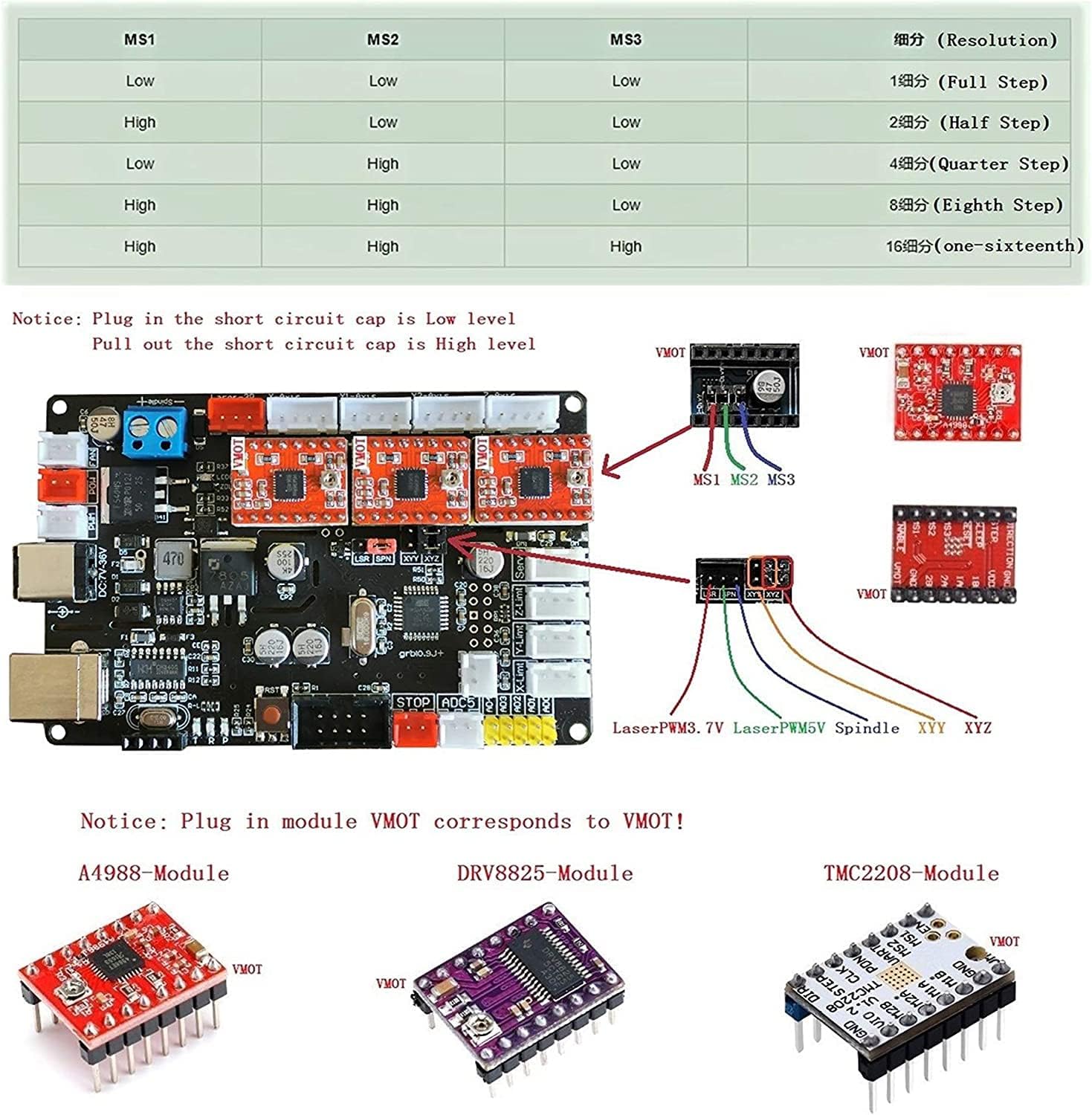
The four white 4-pin headers along the top are the stepper motor outputs, fed from the three stepper motor drivers.
The other connectors are likely limit / home switch inputs.
At this point, it seems you have a machine that has not worked before, has been “upgraded” in ways we do not know, and perhaps has firmware with an invalid hardware / pin configuration.
I initially thought the symptoms pointed to a hardware fault, but the number of variables has exploded to the point where I doubt that’s the case.
I must defer to other folks around here with more experience coaching folks up the learning curve you’re facing.
Paging @berainlb: what do you think?