I have had no luck getting this machine to fire the laser. I’m running a DSP Lightburn version 1.4 something. The software sees and connects to a Ruida controller. Through LB i can manipulate the machine fine. I’ve run a file and ran a material test. The machine does ‘everything’ except fire the laser. When i push the pulse button, there is a beep, but I don’t see it fire. I have water in the tube and air, but I don’t see safety switches for them. I can only find one magnetic interlock on the top lid. The red light on the top right of the controller is blinking, is that bad? I have cleaned the connections as best i could on both ends of the laser. Can i check a voltage at the laser directly?
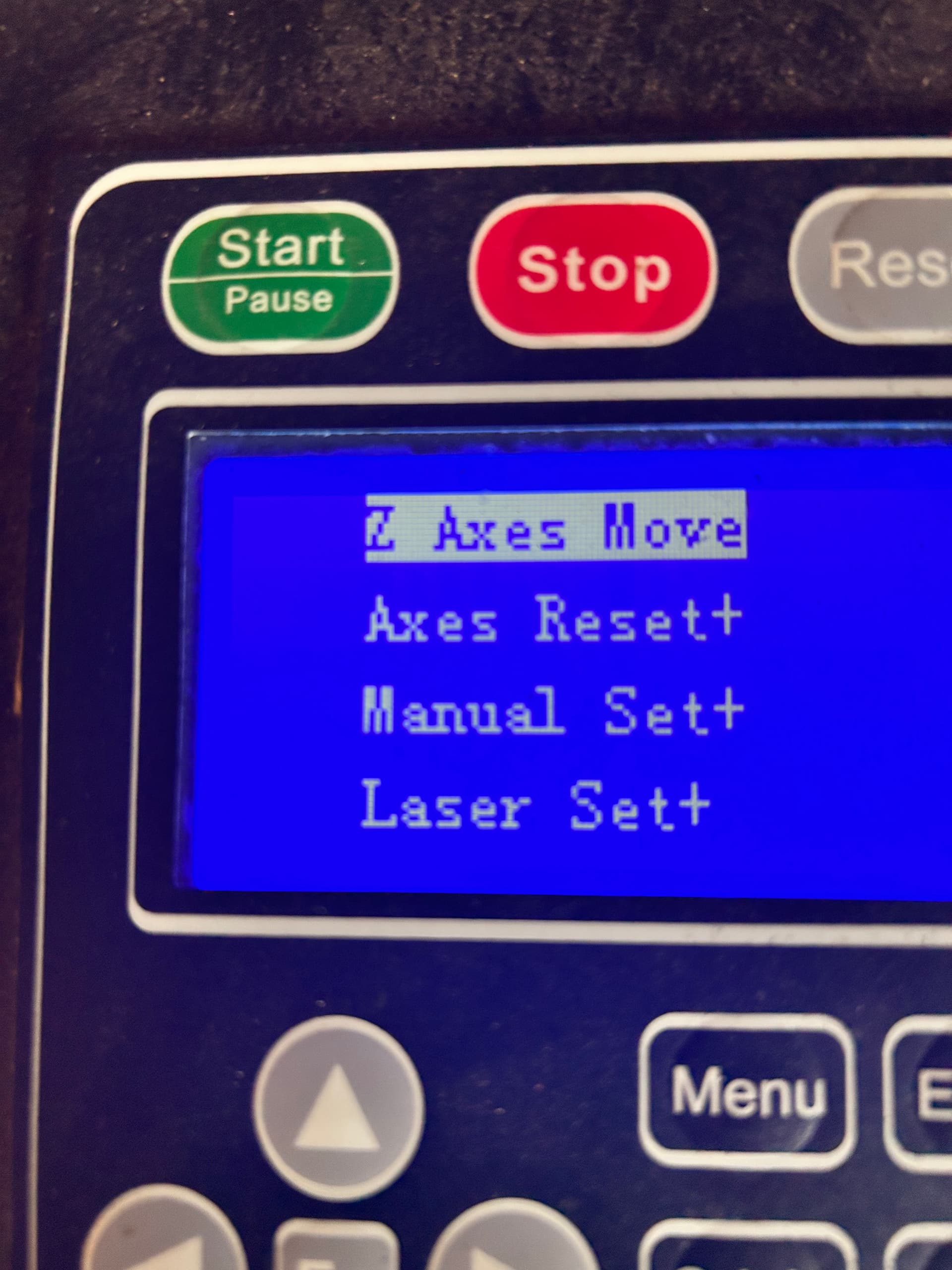
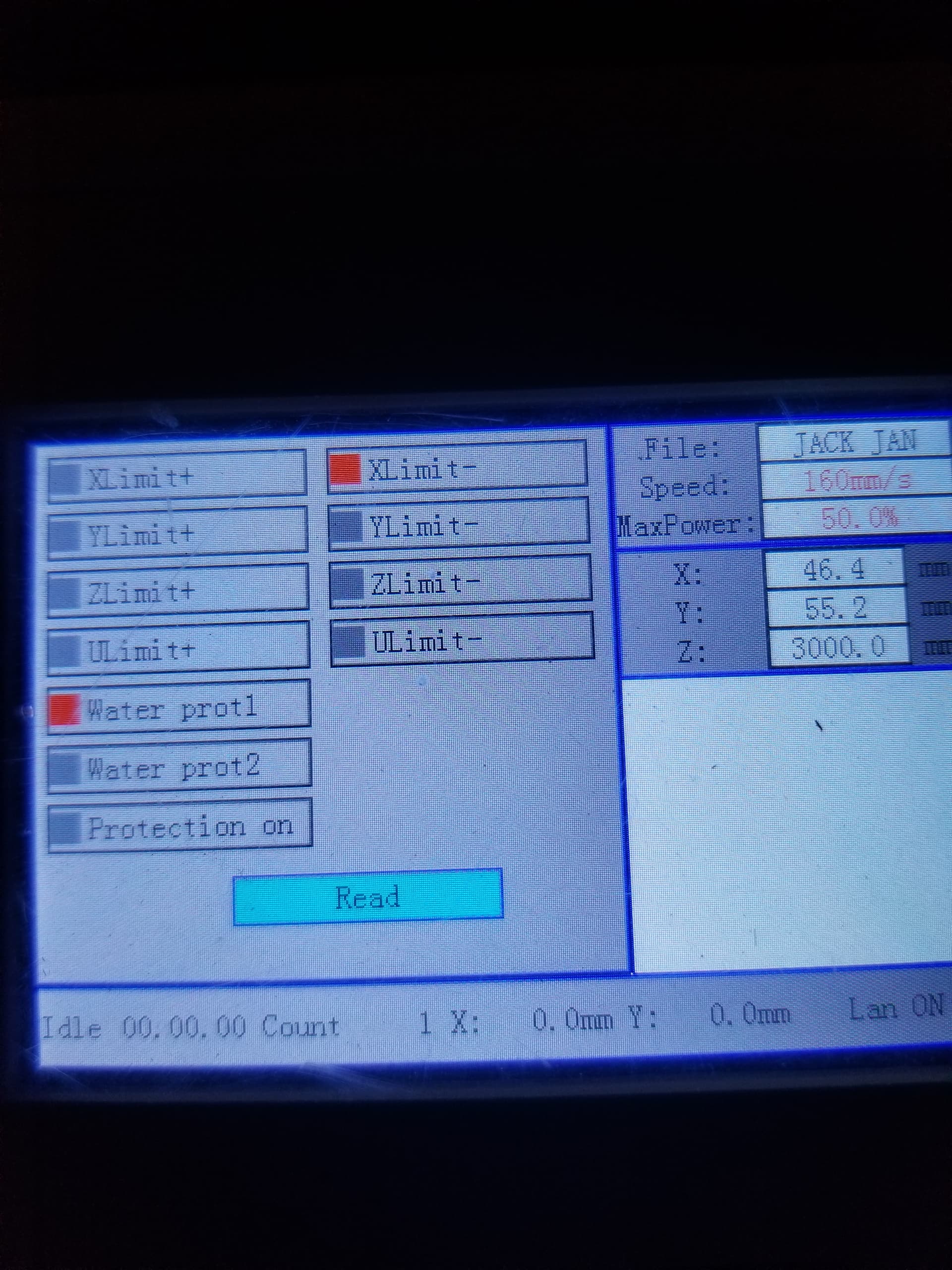
The Menu on the controller button should produce a screen with a Diagnoses (or something like that) choice. If so, select it and you should see indicators for all the inputs, like this:
I went through the menu and functions. I never saw a page that had any similar info like expected. But I did find a red Test button on the laser. I was excited that the laser worked and fluoresced, I kept pressing the button and blew a hole through a half stack of Post-It notes I had left in front of mirror 1, I had forgot about. Good news is that after i put out the fire, I found the water something sensor.
I traced the wires from the top lid switch and the water something switch down to where they terminate on the controller card. I believe the water switch lands on P of the H L P G IN 5V terminals. I dont know how to jumper them out exactly and or what voltage to use.
Thanks for the buzz kill tip of not checking voltage at the tube. lol.
It’s … interesting … the machine says it’s 40 W, but has an MYJG60S power supply typically found in 60 W machines. Unless the seller has done an atypically good configuration job, that supply will severely overcook the tube. Worry about that later.
Don’t jumper anything out!
The (presumably similar) MYJG60W manual may be relevant.
CAUTION: the three terminals toward the top of the power supply carry 120 VAC line voltage. Stick some tape over those bare terminals and pay attention while you’re probing the signals in the other connector.
With the water pump running, the P terminal on the power supply should have about 0 V with respect to the adjacent G terminal. With the pump off, P will be about +5 V.
Trace the wires from the lid switch to the controller: one should be on a GND terminal, the other on a terminal labeled DrProc in the manual. With the lid open, the second terminal should have about +5 V with respect to the GND terminal. With the lid closed, it should be about 0 V.
If both of those signals look good, then it’s something else …
The 6 pins on the left are on the controller card, only 3 pins are used. Using G on the laser card for ground, I found 5V at L P and IN. and at PIN1 and PIN5.
So, 5V at 5 spots regardless of door open or closed. I’m stumped unless the logic is backwards to what i think. It also doesnt follow the example very well, unless they tied all the safty stuff to the input for the foot switch.
The terminal numbering is backwards from your diagram, but the connections for what they call CN6 make sense:
L-AN1 = Analog control of laser power
L-ON1- = Low-active digital laser enable
LGND = ground / common to power supply & sensors
The Door sensor and the Water flow sensor seem to be wired in series, so that the P terminal on the power supply will be pulled low when they’re satisfied.
The Rotary connection makes no sense, because it’s in parallel with the Water sensor. That means when either one is satisfied and the Door is closed, the laser should fire. I do not understand why that makes sense; the Rotary should have nothing to do with the Water sensor.
However, the fact that you measure +5 V on the P terminal explains why the laser is not firing: one of the sensors is not satisfied, so the series connection is broken and the P terminal isn’t pulled low.
If you didn’t have the water pump turned on, then the Water sensor wasn’t satisfied and the circuit is working as intended. Turn it on and the P terminal should be around 0 V.
If the pump was running, then the problem could come from a defective sensor / switch, a broken wire, or a bad terminal connection. Given that the machine dates back to 2018, things like that happen.
Or the mysterious Rotary is something other than a simple switch.
You are correct, they do make sense with numbers being opposite. I am going to assume the water sensor has failed. Is a generic version from Amazon as good as any?
The verbiage they used to explain the footswitch still has me confused, they said to think of it as a ‘pause’ button. Those wires terminate on 2 pins of a four pin connector. Like to attach a rotary chuck and footswitch for cups.
Would taking the water sensor out of the circuit simulate if it were working properly only leaving the door to be the problem? If so, simply combine the wires that go in an out of the sensor, or the opposite, where it didn’t pass power?
Thank you so much for your help. This boat anchor might make it yet.
That’s kinda-sorta consistent with the description of the terminal on mine: push to start, push to pause, push to start again. Haven’t wired it up, because it doesn’t do anything I need doing.
AFAICT, though, the foot switch should not be wired into the door / water sensor circuit.
I tested both the water switch and rotary switch separately.
One wire to ground and one wire to P. Each still showed 5V from P to G when energised. Pump on or off.
I tested both for continuity, neither pass power in what should be a “go” state. (pump was running and no rotary switch attached)
I tested the door switch the same, by itself. It showed 5V door opened or closed from P to G. I didn’t expect that, Maybe I should repeat that test. The door did show continuity and passed power when closed, did not pass power when open.
With one leg of the door switch to ground and the other on P, with the door shut the ground should have pulled P low, as you say. I might have done something wrong in the testing because i had it something wrong. It was like the control power circuit didn’t tell the laser to even power up.
Picture: Door switch on the left. Brown wire goes to GND. Blue wire feeds the two black wires for the rotary and water switch. Two red return wires from the switches land on P.
Those two shouldn’t both be true, because the P terminal should change depending on the door switch’s continuity to ground.
Retest that by itself between G and P on the power supply and see if a better connection improves the results. If it doesn’t pull P low, something is definitely wrong.
If the water switch is open = no continuity when the pump is both running and not, then I’d say it’s kaput and a replacement is in order.
I still don’t know what the rotary switch is supposed to do. For simplicity, leave that disconnected until we figure out what’s going on.
If you promise to never leave the lid open and always keep the pump running, you can jumper the P terminal to the G terminal, thus bypassing all the safety interlocks and protections. If the controller can fire the laser in that condition, then the machine isn’t totally worthless.
My previous test of the door switch was wrong, as suspected.
The voltage on P is 0V with the door closed and 5V open. I was able to use the PULSE button on the display to fire the laser, with the door safely closed of course!
I got 2 dots on the wood for every pulse, hopefully that is only a mirror3 problem.
As long as you remember to always run the water pump, you’re in business until the new flow switch arrives.
That may be a Bad Sign™, particularly given the age of the machine, but let’s find out.
You have a beam combiner!
An extensive discussion has more info:
Two cautions:
The ZnSe plate in the combiner is fragile and won’t withstand scrubbing
The “weak” reflection of main laser beam from that slab carries a damaging amount of energy (to the left in that picture), so don’t get in the way
With that in mind, go through a complete beam path check.
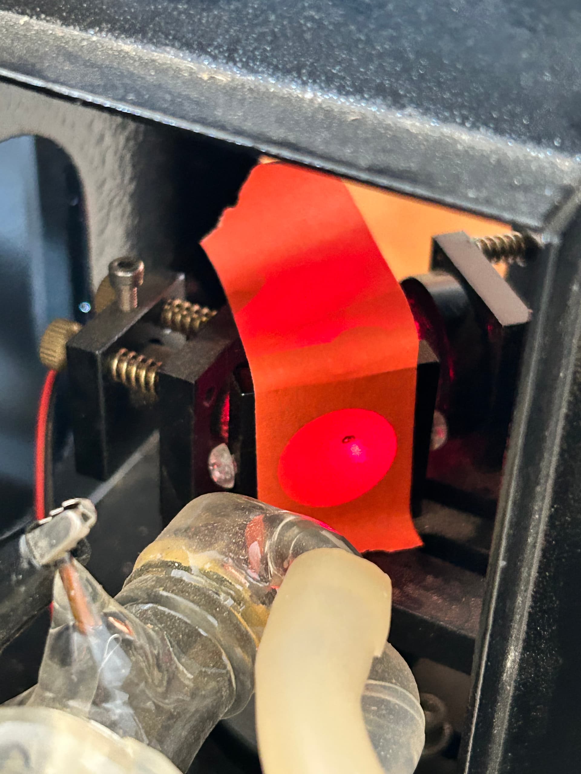
Start by taping a piece of paper / thin cardboard over the entry to the beam combiner, use a manual pulse to put a light scorch on it, then verify it’s pretty much centered. You’ll surely need to weak the manual power / duration to scorch rather than burn.
Verify the scorch is a nice rounded spot (somewhat elongated due to the 45° angle), rather than some weird pattern. If it’s smooth and round-ish, then the two spots on the platform are likely due to beam misalignment that you’ll fix. If it’s weird, then the tube may be kaput.
Repeat for all three mirrors and, for M2 and M3, check at both ends of the axis travel.
Adjust the mirror angles / positions as needed to center the spots at each mirror. They need not be exactly on center, but if you must ask, it’s not close enough.
Take the tube off the laser head, replace the lens with a disk of cardboard, and scorch. The mark should be pretty much centered.
Put the lens back in (rounded side up), stick some tape over the nozzle aperture, and scorch. The hole should be pretty much centered in the aperture.
Show pix so we can look over your shoulder.
If the machine is pretty much aligned already, that process can go fairly quickly. My machine was badly aligned right from the factory and, when I eventually fixed it, turned into an adventure:
The next several posts go into more detail than anybody should really care about, but now I’ll remember what I did.
High to the R on the combiner. Then a direct M1, M2. M3 check. I kept having to increase the power to mark the tape. A 10 second PULSE at 23% power barely marked the tape on M3. It’s not easily visible. put the footprint of the laser mark is dove shaped or sheeps foot shaped.
I ran 2 test. My workspace must not be the correct size on my software to match the machine size yet. Also, the text is mirrored. I’m sure that is an easy fix somewhere. What did bother me is the double print on the larger piece. That was black and white. I’m guessing this is the same as the two dots it marked when i test fired it at 100% power.
Should i continue and adjust the tube to get it centered on the combiner, or is the tube cooked?
That’s an absurdly long pulse for a 40 W CO₂ tube. My 60 W machine gives a good scorch with 50 ms at 50%.
Which strongly suggests the tube is on its last legs.
That’s a Bad Sign™ I hoped you wouldn’t find. A long discussion of what’s going on has more details:
The mirrors are badly in need of alignment, with the spot at M3 being so far off-center the beam may be splashing inside the nozzle and creating a second burn beside the main focus spot.
You may as well go through the whole mirror alignment process, just for practice. This discussion covers some key details:
If the thing still burns a double dot with the beam going right down the middle or it still requires tens of seconds to get the job done, then it’s in need of a new tube.
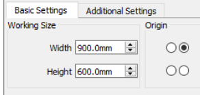
There are two places for that. The first is telling the controller the platform size, which should already be correct. To check, go to Edit → Machine Settings in the Vendor Settings sections for the X and Y axes. I don’t know what verbiage your (oddball) controller will use, but the manual says:
scope: it means the farthest distance that the motion axle can move, which is determined in accordance with the actual condition of the machine.
The label on the back of the cabinet says 600×450, so set those for the X and Y axes, respectively. I expect they are already correct, but now we both know.
When you turn the machine on, it should home to one corner of the platform and stop. If it doesn’t home properly, then there’s another problem to fix.
Assuming it behaves properly, then go to Edit → Device Settings and click the Origin dot corresponding to that corner. The machine in the sample above homes to the rear right corner (as does mine), although anything is possible.
Some of that is due to the double-dot problem, but a large part comes from not having the Scanning Offset Adjustment set up.
You’ve got enough on your to-do list right now, so let’s not open that particular can-o-worms.