Autofocus crashing laserhead into workpiece

Hi there,

I have a problem with my Gweikecloud RF lasercutter. I have enabled Z-axis in device settings to be able to control the laser focal point through Lightburn.

When I move the Z-axis down from the “move” window, followed by starting a printjob, it works fine. The machine will finish the job, moves the Z axis back up, and the printhead goes back to its home position afterwards.

The issue becomes apparent when I enter a Z offset (-5mm in my case) within the cut settings editor (instead of manually clicking on move z axis everytime before a print), the laser will actually move the head down and starts lasering. The problem appears right after the actual print is finished. The laserhead now moves al the way down, crashes into the workpiece, moves back up after which it will home all axis again.

Hopefully someone can help me with this.

Sven

Is “Optimize Z Moves” enabled in Device Settings? If not, try enabling that.

That didn’t work. I also tried “optimize Z Moves” on/off with the “Relative Z Moves” toggle on/off.

What basically happens is at the end of a layer with an offset, the laserhead moves up a few millimeter, and then moves all the way down.

When I use multiple layers, the laserhead will do the same thing when it finishes the laser with z offset. But because the laserhead is all the way down, it starts scraping the laserhead over the workpiece as it moves to the next layer.

I also tried what happens if a layer has multiple passes combined with a Z-step per pass value. These steps work fine for each pass, until it finishes the layer and the problem happens again.

If you enable both “relative z moves only” and “optimize z moves” then disable the z offset in cut settings, how the does the laser behave when burning?

Is there any z movement at all?

Can you explain the process for how you focus the machine?

If I do that, the laser behaves normal, out of focus though. It makes the intended moves and then moves back to home position. It doesnt go up or down.

The way I focus now is calculating 17mm minus the material thickness. The resulting number in millimeters is used to lower the laser head within the move window. After the intended moves, the laser head moves up and goes to home position.

I made a video where you can see what goes wrong. You can see the laserhead move up a little, then down all the way, followed by all the way up again and going to home position. I removed the honeycomb to prevent damaging anything.

Video: WeTransfer - Send Large Files & Share Photos Online - Up to 2GB Free

If you have no movement with those two set I’m not sure why you’d be getting excess movement with the offset. It should literally only move the incremental amount.

Not sure if it’s just me but I can’t seem to get to any video in that link.

That’s exactly why I don’t understand what is happening. I also tried the focus wizzard within LB and that also moves the laser head all the way down after the first line.

I have 15 years of experience in 3D printing. If something happens there, you can check the gcode for anything strange, but there is no gcode to be found in LB. At least not that I can find.

The video is available as a download.

Ruida controllers do not use gcode for operation. LightBurn does support gcode for gcode based controllers.

I was able to download the file.

Looks like this other user had the same issue:

I have have the same issue

This may be of interest to you guys.

  1. Read through everything first - Pay close attention to how some Values are in the NEGATIVES!
  2. From the Machine Settings Window - Make a BackUP of your Config using [ Save to File ].
  3. Consider reducing the change of the Z-Axis Maximum Travel Distance change from 25mm to 18mm as an optional Safety Feature ( the Use of a Rotary may require for it to be left at 25mm )
  4. Remove the Honeycomb Bed when doing the first Tests to confirm it is working as expected.

I think I worked this out so that it moves down at the start of the cut, and moves straight up to the home position at the end. I haven’t had a crash yet doing this. (I’m still new to my Gweike cloud, so I’ll update this if I get more info).

To set up the Gweike Cloud Pro with LightBurn;

  1. Plug in usb cable from laser controller to computer. (note: there are two ports, one for the camera and one for the laser controller)
  2. Install drivers from Gweike website as per this video: How to use Lightburn with Gweike cloud - YouTube
  3. Open LightBurn
  4. Laser window>Devices>Find my Laser (Ruida 644xg, rear right)
  5. Laser window> select correct comm port and Gweike Cloud/Ruida machine you just set up
  6. Edit menu>Device Settings> Enable Z = on, Optimize Z Moves = on, Relative Z moves = off
  7. Cuts/ Layers window> set Material (mm) to 17-thickness of your material (e.g for 3mm ply, you would calculate 17-3=14, therefore put 14 into the Material(mm) field.
  8. Enter material settings: GweikeCloud Parameters Setting Table
  9. Design/frame/cut your thing.

==== Notes ====

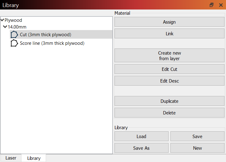
Saving to the library

When saving to the Materials Library for the Gweike Cloud Material Library - LightBurn Software Documentation you need to enter the Material (mm) value (e.g. 14 for 3mm ply) into the “Thickness” field to preserve it with the settings. You may wish to note the real-life material thickness in the field of the Material name or Description, for ease of recognition:

Z Offset / Z steps per pass
If you want to use these settings (e.g., to defocus a bit just while doing raster engraves in a job where you have cuts and engraves (offset), or to move down into the material with each pass in a thick material so that the cut is better in focus (steps per pass), they can be accessed via the cut settings editor (double click on the layer). The main thing to note for the Gweike Cloud is that THE DIRECTIONS ARE REVERSED. Do NOT go by the in/out indicator in the dialogue.

A negative value will take the laser head closer to the material and a positive one will take it further from the material. If it helps to remember, imagine the Z axis is a traditional vertical one; up is positive and down is negative; a positive value in Z offset or Z steps per pass will take the laser head up, a negative will take it down.

These settings are compounded upon the Material (mm) setting. So set your material correctly first (as above) e.g 3mm ply is 14, then add the amount you want the laser head to move up or down from that height in the Z offset/ Z steps. e.g if you want to defocus a little for an engrave you would put 1mm in the Z offset field (NOT 17-3=14).

Camera Setup
There are two stages to camera set up, Calibrating the Camera Lens, and doing the Camera Alignment.

Calibrating the Camera Lens

  1. Plug a usb cable into the camera port on the machine and into your PC and turn on the laser.
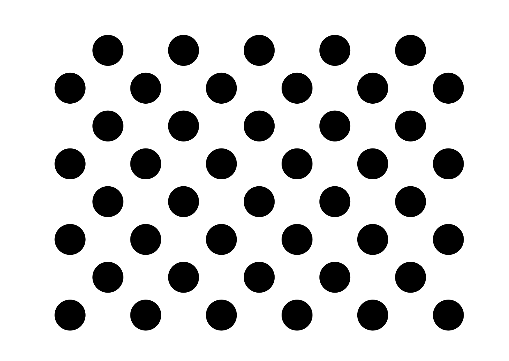
  2. Print the calibration dots at 50% scale and adhere it to something flat (e.g corrugated card) so the pattern isn’t distorted as you will need to prop it up on angles due to the fisheye lens.
  3. Laser Tools> Lens Calibration Wizard > Choose SHUNCCM, Fisheye Lens, no preset
  4. The Cloud Camera is a fish eye, so after the first (flat/centre) capture, you will need to tilt the dot pattern toward the camera to get it to capture correctly (not lay it flat). The camera and dots need to be still when you capture them so prop the card up in the machine against another small object (e.g. a tall stack of post-in notes), to tilt the outer edges toward the camera, and I used the front access panel (the door where you slide the honeycomb in and out) to move the dots around to keep the camera super still. The stock lighting inside the machine is uneven so I also set up two overhead lamps to add some more. I had the best captures when I ensured the dot pattern was upright in the camera view (the ‘top’ of the longer sides has fewer dots than the bottom).

Camera Alignment

  1. The Material Thickness in this menu does NOT move the Z axis, it’s used on the back end for calibration. So before opening this menu you will need to get the machine to move the Z axis to the correct focal height for the material you are engraving. Use the Move window to do this by changing the distance to the focal length of your material (given by the equation 17-thickness) e.g. if your material is 3mm thick, enter 14mm into the distance and hit the Z down arrow (bottom left of the directional keys) to move the head down.
  2. Laser Tools > Calibrate Camera Alignment > Fixed position > SHUNCCM (check you can see the camera feed) and click next.
  3. Change the material thickness here to the ACTUAL thickness of your material (e.g 3mm for 3mm thick ply)
  4. Complete the alignment as per the guide.
4 Likes

I just updated the above with camera set up too.

I’ve done quite a few jobs now with the above techniques, I think I can pretty confidently say it’s working. :slight_smile:

Thanks @BillieRuben Appreciate the info. I think as GWEIKE grows, specific guides like this will really be beneficial to the community.

1 Like

Awesome write up Billie! Have the same issue as the OP. Working through these instructions now and will report back either way on how it works out. Much appreciated!

1 Like

Please do! I’d love to know if it works for others too! I’m in Australia, and sometimes companies send us slightly different models down here, so it would be good to confirm it’s similar. :slight_smile:

Thanks! Did you get yours going after all?

Yea my issue was your post about absolute z. Once I disabled that, focus all perfect now!

1 Like

Woohoo! Great to hear!

Ok, so I’m in the US and I apparently have the newest model of the laser that doesn’t come with the air filter cabinet (it comes with a separate fan/motor/remote). In any case, your instructions worked perfectly but with one distinct difference. I had to use a negative Z value for it to work. Using your example, I worked with 3mm birch plywood for test cuts. Using 14mm as the Z value, the laser head touched down on the material and barely came off the surface to begin cutting. The head was so close to the material that in some spots along the job it actually scraped across the material. I then redid the job but using a -14 Z value and the laser head lowered to what I expected to be the proper height and ran the job perfectly. I ran several subsequent different jobs on the same material with the negative value and it also worked flawlessly. I’m not sure if this is a Gweike or a Lightburn glitch or an expected outcome but I essentially need to reverse the Z value for it to work, In any case, your instructions were very helpful and turned days of frustration into a few minutes of fairly quick troubleshooting. Many thanks and I hope this helps others out there as well.

1 Like