Blue & White 100W CO2 - Parts aren't cutting to the correct size

Hi all,
I got my first laser about a month ago, an HL-yeah 1060z, and I just noticed that the parts are a little undersized from actual dimensions. I’m getting things prepared to quickly swap out lenses (1.5"-5"), so I want to get a baseline of actual movement vs requested, so I can measure and adjust for kerf of each lens.

I pulled out the dial indicator and took some measurements. X and Y both off by ~.004" on a 1" move and back lash was .0025" on X and .005" on Y. I made adjustments to the step length, and back lash settings in the Ruida controller, and then retested, and was getting near perfect readings, within .0002".

Figuring I was on the right track, I cut another part out with no kerf offset. The results are really confusing me:
Part size in light burn: 3.125" x 3.125"
Measured parts: 3.131" x 3.129"
Ruida display: 3.114" x 3.122" (shows 79.3mm x 79.1mm when cutting outer edges)

The part was set at 0,0 for the starting point, and again, no kerf setting from lightburn.

It seems that there is some compensation going on behind the scenes, but I cannot figure out if it’s in Lightburn, or Ruida. Very odd that X and Y are different as well.

Also, the machine was listed with 0.01mm positional accuracy, but the controller only displays 0.1mm precision. I spent 2 hours last night trying to see what moves are being commanded, but can not seem to figure this out from either Lightburn or Ruida, so the controller display is all I have to go on right now. It seems G-code isn’t used by Ruida, but I’m not 100% on that.

I’m pretty stumped on this one, would really appreciate some help on what steps to take next.

thanks,

Brian
You can educate me and advise where to find the backlash in the Ruida controller…? Don’t remember seeing this.

This makes most of us worry… if you just got a new(?) machine and you’re inside tweaking it… so it’d be nice if you can advise us of your technical abilities with these… we could probably save some time.

I would expect no kerf would be smaller than an added kerf. I believe this is computed within the Lightburn and sent to the laser… the Ruida isn’t really too smart at anything other than following a tool path…

@ednisley might have some better suggestions for this than I, so I’ll defer the steppers to Ed.

Try this for the Ruida machine codes


I’m used to working in metric, so inches always kind of throw me. I believe Lightburn internal math is done in mm and I know rounding errors come up, but usually in very extreme areas. Unlikely this is the issue here.

How new is this machine?

I hope you saved the factory setting somewhere safe before you changed them… :pray:

BTW, wecome to the site :grimacing:

Good luck

:smile_cat:

I fear you’re digging yourself into a hole.

Reset the controller back to the way it was; there should be an automatic backup of those settings made before your changes.

Set the controller’s backlash adjustments to zero.

Turn off any kerf settings and disable Hide Backlash in LightBurn.

Set the distance per step value to the exact number calculated from the stepper driver’s step/rev, the number of teeth on the motor pulley, and the belt tooth pitch, thusly:

Verify that setting using a good scale and the red-dot pointer on your laser or measuring the distance between manual pulses in paper, using just the console buttons to move the laser in exact increments:

Use LightBurn to measure the actual kerf in the material you’re using:

Use this test pattern to measure the actual backlash:

BacklashTest.lbrn2 (197.6 KB)

If you can’t measure (or even see) the backlash on that pattern, then it’s (almost certainly) too small to matter.

With those measurements in hand, you may find the machine is working better than you expected.

Let us know what you find.

Jack, the backlash setting is under ‘machine settings → misc’ in light burn, and under ‘user settings → other’ on the controller. Going from memory here as I’m not by the machine now, but they settings are not in the axis settings as one might expect. I’m on V35, and it seems most are on V15 or V26, so maybe this is a relatively new addition

I’ll update my profile to include my CNC experience. In summary, I’m hobbyist, but fairly competent. I can basically make anything work, as long as someone from the internet tells me how :wink:

I purchased the machine as a new unit, so it is ~1 month old. Rest assured, I have backups of everything.

1 Like

Ed, Let’s pretend I never made any changes to settings, and we’ll start at the beginning.

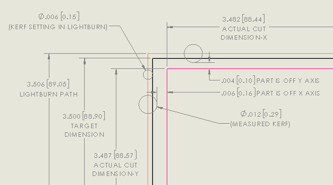
Here’s a part I cut with the machine as received. It is a 3.5" square quilting ruler/template. I had just received the machine and did not have much cut data documented at that time, so my kerf setting was off. The Kerf setting is in lightburn was set to .006", but the actual kerf measures .0115". Obviously due to the wrong kerf setting, I can expect the part to be off, but it is off more than theory suggests it would be. hopefully this picture clears things up.
part cut vs theoretical dimensions

Again, this is how the machine was cutting as received. The positional accuracy was listed as .01mm( .0004"), so it is off by 15x (x-axis) and 10x (y-axis).

Any kind of test file I cut with this machine with it’s original settings is going to be off, so I don’t see any value in making those as the machine currently sits.

I had thought about calculating the step distance as you suggest, but that is going to be quite time consuming. The X and Y axis are different driver manufactures (X is leadshine w/ encoder), so i need to research both of those to determine microstep settings/encoder resolution. The Y axis stepper isn’t in a great position to access either for pulley measurement/tooth couting. Not an impossible task, but will certainly eat up a good chunk of a morning, if not all of it or more.

I’m in the middle of my 4 day work week, so I have limited time to mess with the machine until Friday.

OK, as long as one doesn’t return to bite us. :grin:

I think the basic problem comes from a (probably deliberate, on the part of the laser seller) confusion among resolution, precision, accuracy, and repeatability, producing unrealistic expectations on your part.

That is almost certainly the nominal distance per microstep: one STEP pulse from the controller turns the motor shaft one microstep, which then moves the pulley / belt / gantry / laser head by 10 µm = one wavelength of the deep infrared light emitted by the laser tube.

That’s the resolution of the positioning. The accuracy is much much worse.

Long ago, I wrote firmware for machinery capable of putting a 1 µm laser spot exactly on a 1 µm target wobbling 100 µm in any direction at 60 Hz , but the hardware didn’t cost three kilobucks delivered to my driveway. :moneybag:

The kerf setting should be half of the actual kerf, so your setting is just about spot on. In round numbers, a focused CO₂ beam will be about 0.2 mm in diameter and produce a cut about that same width, so, depending on what you’re cutting, a 0.3 mm kerf is as good as it gets.

You need to know where you’re starting from before you know whether you’re making progress.

The reason I suggested those test patterns & measurements is so we all start from basic values, rather than trying to figure out what’s going on by working backwards from a combination of settings peculiar to a specific layout.

The motor driver step/rev settings are typically printed on the side of the driver housing, which are generally mounted in the cabinet where you cannot see them. With a bit of luck, you may be able to squint around the cables and compare the DIP switch settings with the legends; if not, loosening a couple of screws will provide enough motion to get an eye in there.

Mark one tooth of the motor pulley with a Sharpie, then drag the belt around while counting teeth. I mark every fifth tooth in a different color after the second time I lose count. :grin:

With that in mind:

In round numbers and with careful attention to the details, you can cut within ±0.1 mm of the nominal pattern size for reasonably large objects on any one day.

Mechanical backlash and laser head stability will generally swamp all other considerations. Both LightBurn and the Ruida controller have backlash compensation, neither of which remove the backlash. What the compensation does is to push the backlash somewhere you may not notice it for this job, but will come back to kill the next job. The only fix is to eliminate the backlash by careful tuning & adjustment, with the lower limit depending on the machine’s overall rigidity.

You must measure the kerf for each material / thickness / power level / speed / assist air flow, with the kerf setting = half the measurement.

Day-to-day positioning repeatability depends critically on the stability of the machine’s homing switches. Again, you’re looking at errors on the order of ±0.2 mm, which may require fixture position realignment before starting the day’s most accurate projects.

Bottom line: the machine will generally produce objects accurate to ±0.2 mm of the nominal outline.

But it’s absolutely the best tool I’ve ever owned, right up there with the 3D printer, and I predict you’ll feel the same way.

Also: quilting templates & guides FTW!

Never noticed it in the machine settings… I have a screen shot and looked for it.

I’ve always set Lightburn offset scan adjustment… As far as I know this is done in the software…

Thanks … :grimacing:

:smile_cat:

Ed, thanks for the quilting links. Will have to check them out once I get the machine in order. I spent the weekend measuring, calculating, and making some test cuts. Unfortunately, I’m not making any progress. Before posting those results, I did notice some strange behavior from the controller I’m hoping I can get assistance on.

After machine startup, if I jog the Y axis to zero, it goes to zero on the Ruida display. Then, when I move the X axis, the Y axis jumps to .1mm on the display. This happens if I move the X axis left or right, and happens as soon as I hit the X axis jog button. If I jog Y back to zero, it will zero out again, and I can hear the Y axis moving. After zeroing Y the second time, any inputs on X do not affect Y. This behavior is consistent and repeatable. I do not need to restart the machine for it to happen again. Just need to jog off Y0, then back to it, and X jogs will do the same thing again.

Also, If I jog Y to a random position, then jog X, Y will sometimes move from the current value. This isn’t consistent. Sometimes the Y value does not change, sometimes it changes .1mm, sometimes .2mm. I’ve seen it change value in both positive and negative directions. Rough guess, the Y axis value changes 40%~50% of the time.

Also, I have not been able to determine a way to view the position from the controller, other than the display, which only has .1mm resolution. Is there any way to view this through lightburn or RD works? Either with a cut file or otherwise.

thanks,

That seems wrong.

On my machine, the X and Y coordinates are 0.0 after startup, because the controller has homed both axes and set them to 0.0. The position after homing can be moved a few millimeters inward with the Home offset setting [*], which is 0.0 here. With homing disabled, the default coordinate becomes 10000 after a reset at whatever position the laser head is at.

What are the X and Y coordinates after your machine homes?

The laser head should move to the right rear corner, activate the home switches, back off, tap them again, and stop with the coordinates at 0.0 plus any Home offset. If it does not do that, then something fundamental is kaflooie in there.

We’ve had reports from folks where the Ruida controller did not home correctly, no matter what they tried, and required replacement. You may have one of those duds.

[*] At Edit → Machine settings → Vendor settings → X axis if you’ve never ventured there before.

The homing routine seems normal. The machine is set to return to the part origin after homing. I know my x home offset is 1mm and y is 0mm, but I’m not sure that has any effect on what im experiencing. All these settings are the factory settings.

If the Home offset values for X and Y match that, then it’s all good.

Perhaps the X home switch is 1 mm too far to the right and lets the beam hits the edge of the platform, so they pushed it slightly leftward.

Do you still have nonzero Backlash settings in the controller? If so, it’s probably taking up whatever backlash you set in anticipation of the next motion. That would account for “Rough guess, the Y axis value changes 40%~50% of the time” because half the time it’s on the wrong side of the backlash.

Which, IMO, is why you do not want to compensate for backlash in the controller; set those values to zero.

If the Backlash values were zero, then that is not normal behavior, period, and can account for all the positioning problems you’re observing. If it fails during manual jogging, it will most assuredly fail during programmed motions.

Now that you have a dependable way to make it fail from the machine console [*], start a warranty discussion with whoever you bought the machine from, because that controller is a dud.

LightBurn’s Get Position button will display / read / set the coordinates with 0.01 mm resolution, but the physical position will be (at least) ±0.1 mm away from that exact value, roughly the radius of the focused laser spot.

I do not know how to say this more politely, but you will never ever get better than ±0.1 mm positioning accuracy from that machine, so stop worrying and love the error budget. :grin:

[*] With zero backlash settings and without involving LightBurn, because sellers always blame LightBurn for any problems.

I did have backlash values in the machine, and removing them eliminated this behavior. I’m not sure why this would have an effect, as I’m not moving the Y axis when it changes value. Just to test, I set both X and Y to the same backlash, and then tested for the behavior on both axis, and only Y displays this behavior.

Thanks for letting me know about the get position button. I had no idea that existed. I’ll certainly make use of this for further testing.

The vendor is currently building/testing a Z axis lift kit for me, as my table was wobbling around in the X/Y plane by .020" when raising/lowering. I’m waiting for that to get in the mail before reaching out to them.

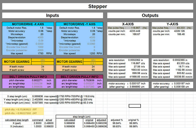
Here’s the values I calculated over the weekend, BTW. The design criteria I recall is the axis resolution should be 10x (or 1/10?) the desired positional accuracy, which should put me in the .0025" range. .008" seems too much to me. I think that rule was for servo’s and ballscrews, so maybe with steppers and belt drives, it may be different. I guess my next steps are to find and reduce the backlash. and take it from there. Appreciate the help on this.

Also, I’d like to mention that I paid 5K for this thing (after shipping), not 3K. There were 3 or 3.5K machines with higher wattage tubes, but I choose this one primarily for the increased accuracy. I thought I was getting closed loop steppers on both axis, but misread the listing, and that is only on the X axis. In short, I paid extra for more precision, and apparently didn’t get it. I hope that helps clear up some of my expectations and frustrations.

Again, I appreciate you assisting me with this. I know this has nothing to do with LightBurn, but it seems to be the best forum for Ruida controllers. All my searches keep bringing me here at least.

There is a very good site that targeted RDWorks software, the factory Windows software for the Ruida… It’s called RDWorks Learning lab.

Not Lightburn, but a good source of Ruida information. You may like it.

:smile_cat:

Cool, thanks. I’l have a look see

IMO, unless the “closed loop stepper” has its loop closed through a linear scale feeding back the actual laser head position, it will be no more accurate than a cheap open-loop stepper, because essentially all the slop occurs in the drive train from the motor pulley to the focused dot.

If the encoder is on the stepper shaft, it makes no practical difference in the positioning accuracy out there on the platform. It does have the advantage (for the seller) of adding an attractive bullet point to the description, which drives the price up without adding too much to the unit cost. :frowning_face:

Most of these just count steps… closed loop can correct if they loose step(s). That’s what I can pick up out of the documentation and discussions on how they work…

If the step distance is much less than the kerf, are you gaining anything?

:smile_cat:

Maybe bragging rights.

The usual Ruida config on a cheap CO₂ laser seems be (within a factor of two of) 10 µm/step, below the usual stiction limits for the linear guides. So you can command 0.01 mm motions, but the laser head won’t move until the total exceeds maybe 0.05 mm.

Measuring the absolute XY positioning accuracy over the entire platform would be an interesting exercise, but I have no idea how to do it with any instrumentation I could afford. :grin:

That’s why the government has technology grants… :crazy_face:

:smile_cat: