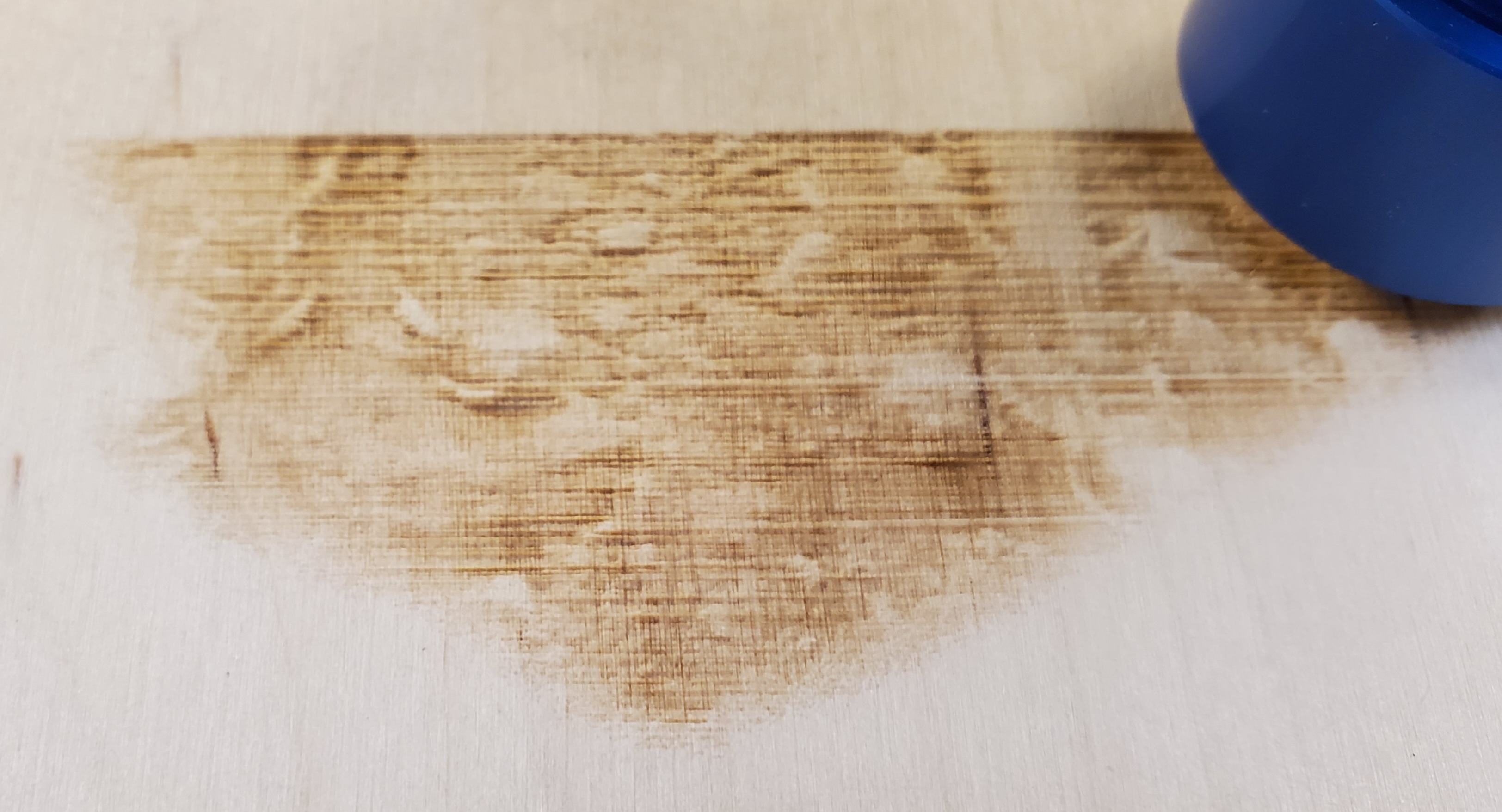
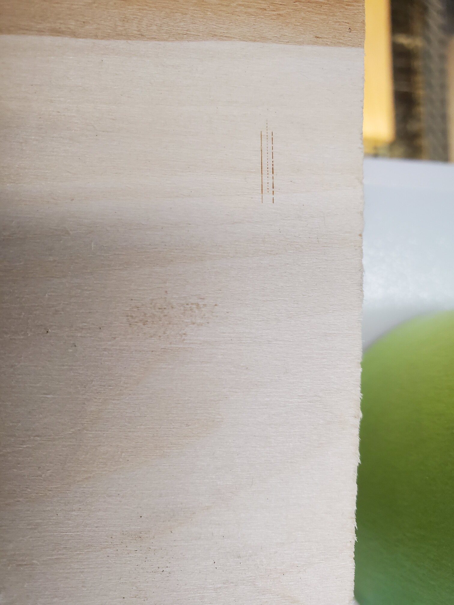
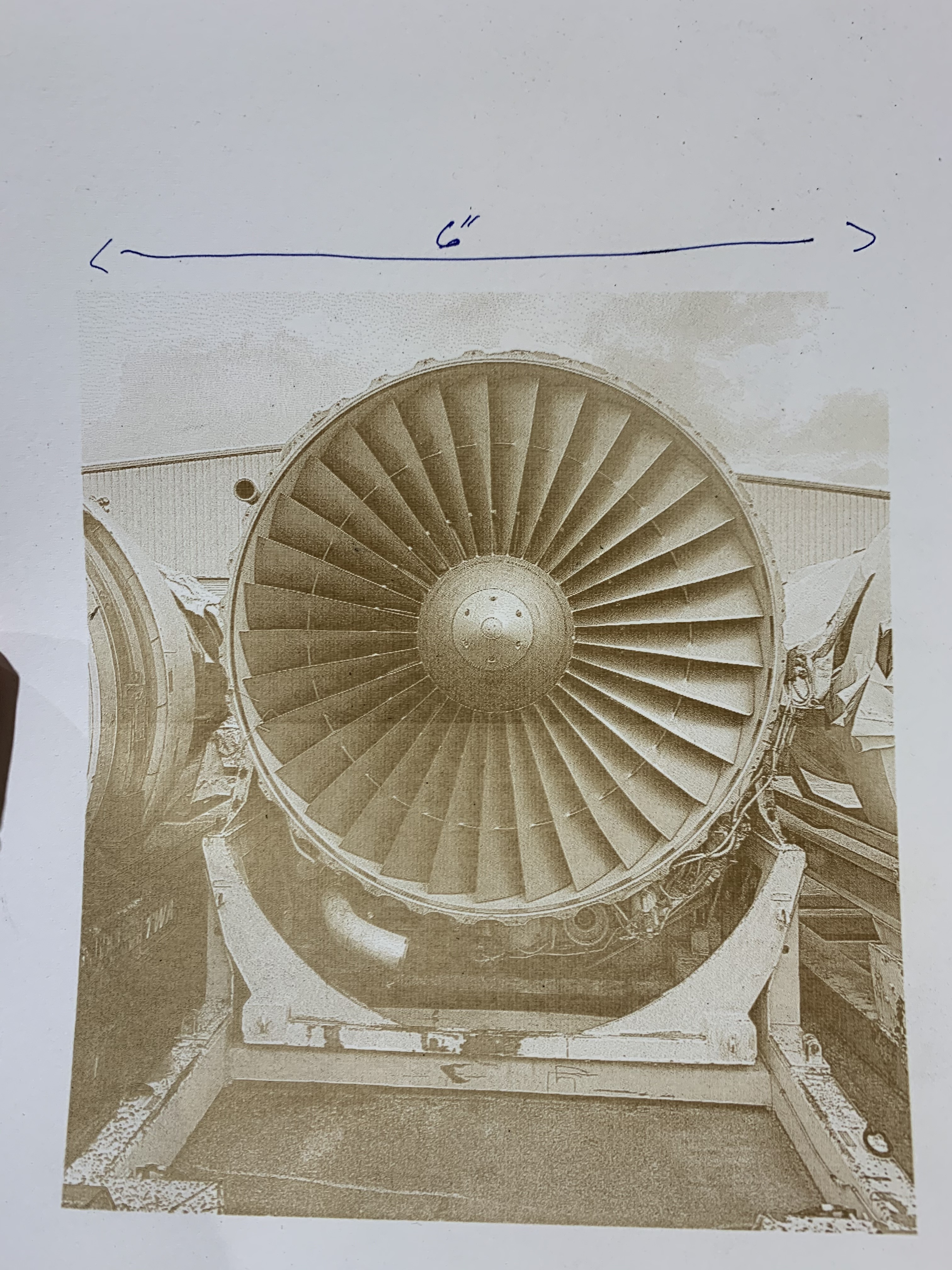
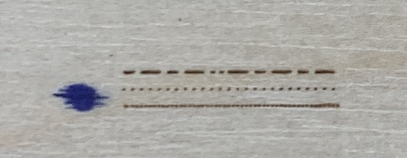
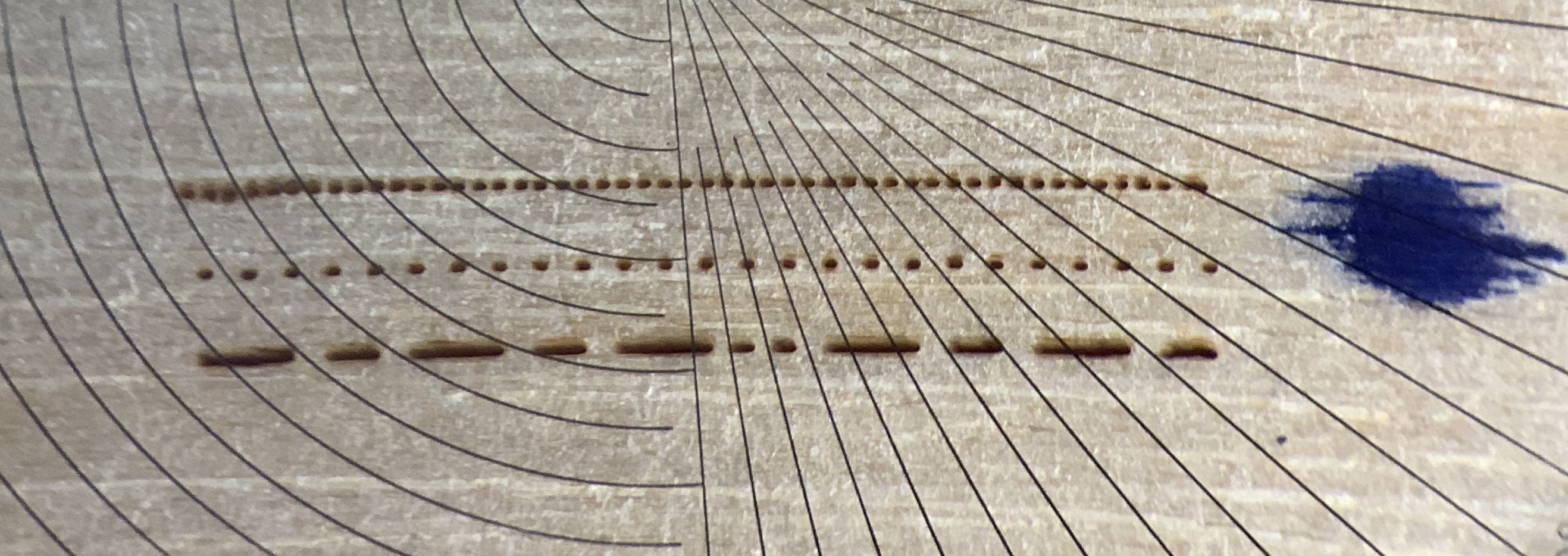
That’s interesting. It looks like your middle line is way offset from the top and bottom lines. What speed and power are you running this at? What is the length of any one of those lines on the material? Hard to judge scale without something in the picture to get an idea.
Without seeing a more magnified picture, and knowing what I do about that pattern, I’ll give you some analysis. In the original file all the pixels are .1mm. On the bottom line the pixels are spaced so that the center to center distance is .2mm. On the middle line the pixels are spaced so that the center to center distance is .4mm.
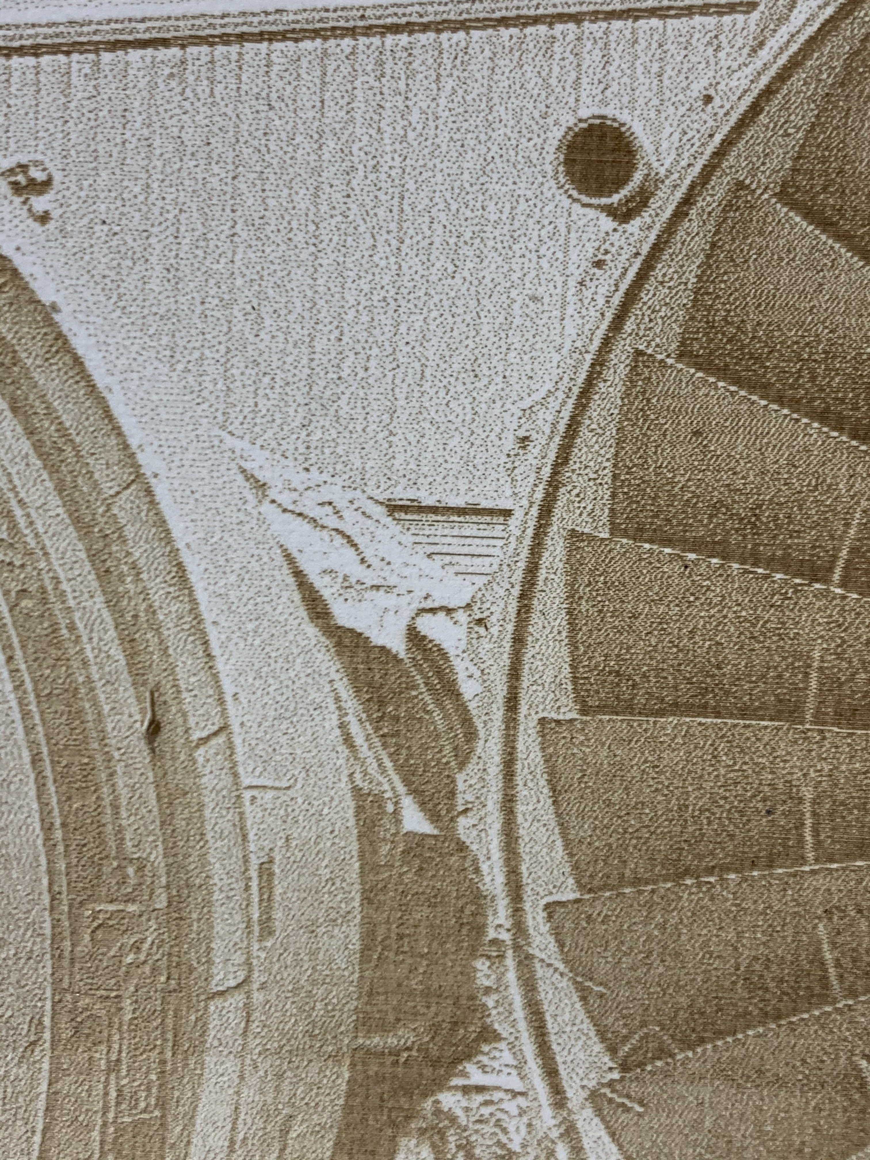
From your image it appears that bottom line of dots basically touch each other to make what appears to be a continuous line. In the middle row of dots it looks like you could fit another dot in the blank space between each dot. So if you think about that, it means that you’re putting down dots that are .2mm in diameter. If that’s the case then the highest DPI you’d want to run would be 127DPI or a .2mm interval. On that bottom row there’s a tiny section where you can just start to seem what appears to be white space between the dots. So you might estimate that they’re .18-.19mm in diameter.
I’m confused by the middle line being offset so much. I’d suspect that you ran this at a high speed or you’ve got some pretty good backlash somewhere.
A couple of things to try. Figure out the minimum power your laser will fire at and use that for your power setting. From there adjust your speed to try and achieve a dot on the middle and bottom line that’s as dark as the dashed lines on the top row. My guess is that this will slow your speed down from your test considerably. Reducing the power to minimum should also hopefully get you a slightly smaller dot.
To figure out what’s going on with that middle row try turning off bi-directional scanning and see if all three lines then line up
Also, if you have a moveable Z, take note of whatever your current Z height is. Use the jog buttons (in Lightburn) to increase the Z height by .1 or .2mm at a time and run the pattern again to see if you can get your focus any better (smaller dots). Then go back to your original Z and try decreasing by .1 or .2mm at a time (same thing in the other direction)
Basically, if you can get the bottom row to look like dot, white space you could fit another dot, dot, etc. then you’re getting .1mm dots and you can set your interval to .1mm. If the middle row looks that way then you’re getting .2mm dots (and therefore interval). From what I see, your middle row seems to look that way.
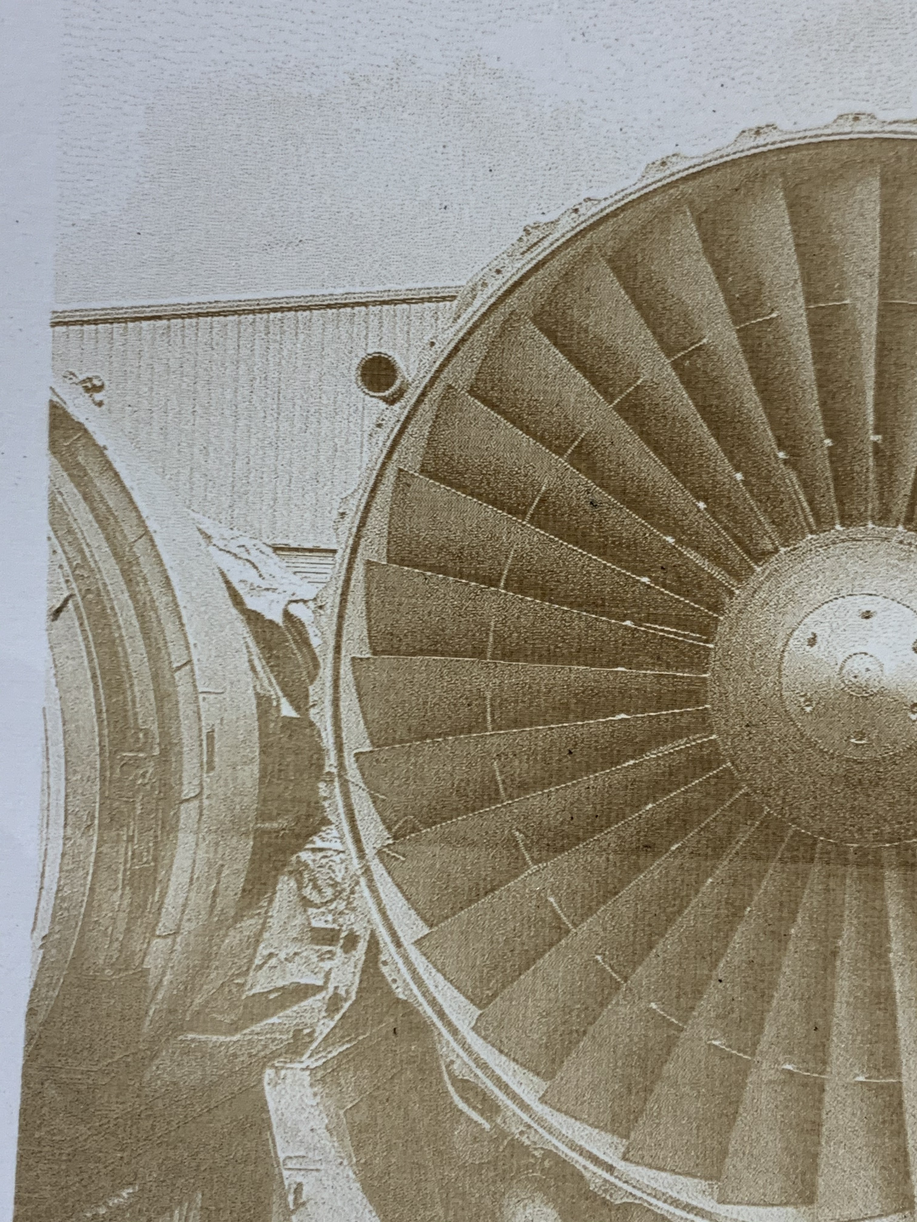
My understanding is that some modes (newsprint? halftone?) are more forgiving with overburn but to me they look “stylized”. For a more photo realistic looking result you’ll want to use jarvis or stucki with your photographs. But using jarvis and stucki you’ll get overburn if you set your interval any smaller than your dot size. When you zoom in close you want to see actual dots making up the engraving.
What you have there is not a bad result to start off with. What wattage is your tube?
Also, I asked a couple of times but never saw you respond. What is the resolution of your original photographs? Presumably they are bigger than 720x960.