How to set up the SKR 1.3/1.4 Board with the K40 Laser

The controller is connected to the power in series with the resistor dial to the IN pin on the psu.

You set your upper PWM limit on the board, so you can’t get more power than that upper limit. The dial controls the output of the board, giving you override control over the output, but no higher than the max output set in your PWM config.

1 Like

your k40 has a “analogue” potentiometer, right? Mine has a digital panel, but I am thinking of getting rid of that in favour of just simple pot. Alot easier to setup in series with a controller…

Mine has a digital panel. They do the same job as an analog dial. No need to double up or replace something that works. The downside to the digital display is the power drain on the very marginal 5V rail on the PSU. The 5V output has only a small amount of mA to work with - and everything else you put on that 5V rail sucks power and reduces the efficiency of the panel power control. A $10 5V switch-mode psu takes the load of the K40 PSU, and delivers a much cleaner supply, without the likelihood of ‘browning out’ due to excessive drain.

When converting K40s, I add in a 5V psu, a 24v PSU and leave the existing PSU only for laser power. The controller/steppers are powered from 24V, the accessories by 5V, the power to the panel comes from the PWM output by the controller. I don’t have an SKR, so I can’t say how robust their 5V transformation is.
The panel should be set to 100% and ignored for the purposes of overall power control, except when you want to override the power down, for some reason. All power management should come via the controller.

The process is:

  • Set your controller to give 100% PWM output.
  • Put a multimeter on the ground side of your tube to measure the mA
  • Adjust the panel to the setting you would use to reach the maximum power allowed by your tube - for arguments sake lets say it’s 15mA.
  • Measure the PWM input to the LPSU ‘IN’ at that setting - that gives you the maximum PWM output that matches your panel setting. That is the maximum power you want output by the controller.
  • The PWM output from the controller goes via the panel to the IN pin. The panel only acts as a manual limit on the controller output. It cannot go higher than the maximum PWM configured in the controller, but it can cut the power.
  • So, if you tell the controller to run at 80%, with the panel at 100%, there is no change to the PWM output by the controller. If at 50%, in theory it should deliver half the PWM output, but it never seems linear.
  • You can calibrate it using a multimeter, stepping from 5% to 100% in 5% increments and reading the mA out of the tube.

In normal use, you would leave the panel at 100 and all power is controlled by the controller, via the job submitted, just as my RuiDa-controlled machine has the dial operate on adjusting the power level for the current job - so my job has me cutting at 85% power at 100mm/s, but I wind down the dial because it’s a little too fierce. Not something you do every day, but I occasionally use it to run a second pass at lower power if the part didn’t release cleanly or if the engraving is too hot.

The main difference is that on most bigger machines, the LPSU has a pot inside that you can adjust to meet the maximum power recommended for your tube, and the cheaper ones that use the K40-style PSUs don’t. Just a LOPT that boosts whatever signal up to whatever output. That’s why K40s are easy to burn out the tube - there is no way to set an upper limit on the LOPT (Line Output Power Transformer - the device that puts out 20KV). On an advance PSU, there’s no need to calibrate the PWM output, because you can adjust the upper limit of the PSU.

Of course you could replace the crap multi-volt PSU that comes with the K40 with a better 40W PSU with power adjustment, and make things a lot simpler.

Never forget, a lot of ‘info’ written about K40s is from the perspective of a spotty 17 year old in his garage, with little attention to actual electronic theory, figures given and measured, and filtered through the opinions of people that haven’t a clue what they are talking about.

The info from the guys at C3D will be much more informative than anything found on FB or Reddit.

2 Likes

Squid… One thing I’m confused about (same as Yassin): Isn’t that pin pulled high to about 24V when it isn’t enabled? I want to try your method. I never saw this post before today and had worked out a similar solution to Yassin except on a SKR1.4 using the Servo and Probe ports with logic converter on PWM but not EN (since 3.3v is enough to turn it off). I was running Marlin, and it SUCKS for laser, so here I am trying to convert to Smoothie. It was firing with same pin config I had setup in Marlin, but power level control seemed way off. Too dark even at 3% in LB

So you are saying to connect PSU-PWM in pin directly to the Fan Port negative (2.3) terminal? If I read that pin while idle and nothing connected, I get 23.75V ish. Then I connected it the way I THINK you mean, direct to PWM, and blipped power on for half second showing approx 20V. I assume that is too high to apply to the PWM pin since it’s 5V logic? Maybe I’m incorrect about that.

I just don’t want to cook the 5V rail on my PSU or fry my SKR so I don’t want to continue until I understand whatever it is that I’m missing. I’m not a complete dummy but this is making me feel stupid LOL

So what am I missing? I removed the digital pot/control panel months ago when I switched to Marlin from stock so currently don’t have it connected at all. I do have a 10k pot on-hand if I need it… Does the pot have to be connected to pull it down to 5V level? That’s the major difference in my setup, no Pot. It sounds so simple when I read it, but I’m completely misunderstanding something here because this doesn’t seem correct…

But you are not connecting positive pin of fan terminal to PSU, only GND, which is common for PSU and SKR. So it doesn’t really matter how high voltage is on FAN terminal, so long as PWM is only connected to GND pin of FAN.

Hedeon, I get that, yes the POS pin of fan is always at 24v,
But the fan GND pin is also at 24v until the laser fires, THEN it’s pulled to GND. Isn’t that going to toast a 5V regulator on the LPSU or something? That’s what I’m confused about.

I’m gonna re-read this entire post for the 12th time, but it still isn’t clicking for me what exactly is correct. I wish I could see a simple sketch of a schematic or something of the whole setup. The one showing the FET is helpful, but doesn’t tell the whole story. I’m teetering right on the edge of having this connected and having a working machine again, but have hit a wall with this. It’s just the ONE pin holding me up dangit LOL

I guess the worst that can happen is I lose another $50 from killing the SKR or $100 from toasting the PSU, then several days downtime while I wait on a new one.

Guys, it’s simpler than you think.

LPSU Laser switch control terminal is whats controlling the tube’s power. this leg is pulled-up internally inside the PSU to TTL level by the analog pot or digital panel so the laser is OFF by default because the power output is inversely proportional to the laser switch control terminal voltage.

Now, if you connect the SKR fan fet ground leg (do not touch the 24VBB leg) to the PSU Laser switch control terminal you are pulling-down the voltage from high to low e.g. - the more on-time vs the off-time the fet is - the more power the laser output will be. the fet ground leg PWM ground of the PSU Laser switch = lowering the voltage input = higher laser output.

Hope this makes things a bit more clearer.
And whatever you do - keep safe.

1 Like

Thanks for the help BTW

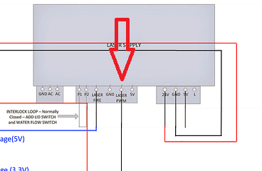
Ok So maybe most of my confusion is about which pin naming and which PSU pins do what… I notice in Yassin’s original image, there is nothing connected to L at all.

It was my understanding (and how I had it working in Marlin) that:

SKR - LPS
PWM -> IN
ENable -> L

Is this wrong? I just spent an hour going over tons of old posts. Some mention controlling power via PWM signal on L and holding IN at 5V. Some have It connected the way I did, Some have “Laser Fire” connected to En as Yassin did. Now I think I may have been doing it wrong all along.

In our current discussion, It says in one comment to connect PWM from MCU to L and another comment says to connect to IN.

Even more lost than before. This whole time, I’ve been using IN to control power level and L simply at 3.3 or GND to enable and disable laser.

So IF I’m understanding you correctly “Laser fire” (I assume is k- or k+ on mine since I don’t have a pin labelled “fire”), and THAT pin should be connected to whichever pin (2.3 in this case) I use for PWM out of the controller board. Then the other pin which is labelled as “PWM” on Yassin’s drawing os the LPS, actually isn’t pwm, but just high/low enable switch from the controller… Am I even close yet?

So the FET should be connect to L, NOT “in/pwm” correct? And use that pin as PWM in Smoothie config, then connect Smoothie Laser_fire pin to the “laser fire” pin. This leaves nothing connected to “IN” in my case.

Is this correct?

MCU - LPS
Pin2.3 - L
FirePin - Laser Fire

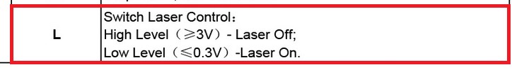
I guess the question is, Which pin is “Laser switch control terminal”?? I have a rough understanding of how PWM and duty cycle works as far as varying a signal and that the lower the voltage, the higher the power on the laser… I just need to know WHERE to put the PWM signal and where to put the On/Off Signal since it sounds like I had it all wrong.

Which Pin does “fire” connect to on this LPS? And do I Leave the In pin disconnected? I know this is a super simple thing, I just don’t know and cant afford to buy replacement parts from guessing haha

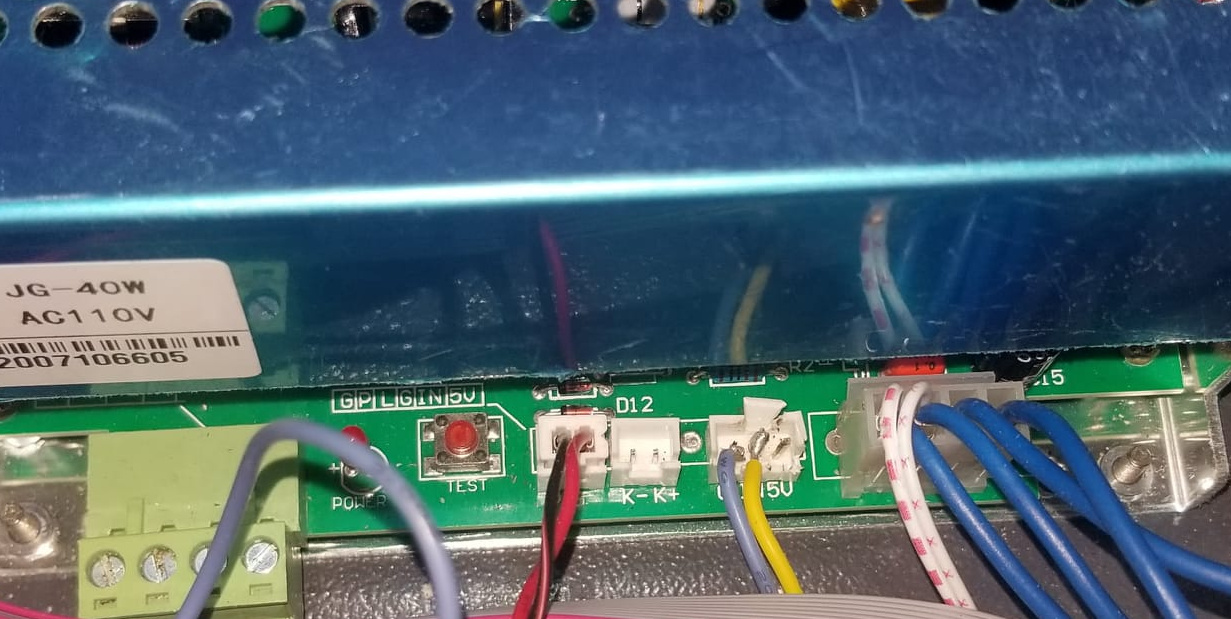
Ignore the crappy soldering, it’s temporary LOL

Edit: OMG I just noticed there are TWO “L” pins The one I have as k-, also has a label showing L, that I never noticed until I sent this photo, The Blue one on the far right is the L pin that I’ve always used.

Thank you Bonjour. It is a lot of good tips to keep me busy this weekend :slight_smile:

1 Like

Are you saying that you controling the laser with just one wire??

No The L on the far right for En and the IN in the middle connector for PWM… Now I think you guys refer to “L”, you are talking about what is labelled as K- on mine… That silkscreen is under the metal and never really noticed that there are TWO pins named “L” until I took this shot from low angle and they are not the same (checked with meter). I think the IN pin that i have the yellow wire tacked onto should be PWM output from controller and the K+ should be enable, but I may have that backward. I saw someone else talking about PWM on the L pin. I guess I’m just gonna connect stuff and see what i blow up. I’m sure any one of you who have it working could look at it and go “OHHH you’re a dumbass, hook this here” In about 3 seconds and I’ll agree LOL

Looks like you are right, I was overcomplicating this. I made a single wire connection between SKR pin 2.3 and L of LPSU and it works. I think I was wrapped in an idea that I need 2 different connections, one to turn the laser ON/OFF and the other to modulate the power output. Even better. A nice and elegant solution. Thanks Squid!.

Now I need to figure out how to scale down LB power settings, as I am reaching 17mA (panel locked to this limit) with just 10% power in LB.
laser_module_maximum_power - seems to have no effect on this whether it is set to 0.1 or to 1

2 Likes

At 100% pwm duty, yes. But you’re thinking is right, it’s the wrong output for your lpsu. If that’s 5he one you’re using, it’s probably why you are at such high output,

This is not something new, it’s very well documented. What does the C3D forum say?

1 Like

Do you have means of checking your fet pwm? it’s always good practice to debug things in the right order of things before getting completely lost in the process. you can try disconnecting the connection to the laser power supply and just see if you can control like the intensity of a 24V led on this fet which will tell you lightburn is controlling this output, then continue to debug the laser/psu side of things. you can also share your laser section in your smoothie config file for us to see if all seems to be in order.

SKR fan fet have a small green led (D8) so you might want to check that while sending different power settings from lightburn.

1 Like

I changed laser_module_pwm_period from 20 to 200 (which seems to be a commonly used value) and this seems to do the trick. Not sure what it does, and haven’t cut or engrave anything yet so not sure how it will perform. One thing I have noticed is that mA output does not scale linearly with the % value set in LB. Is this to be expected?

1 Like

Yes.
BTW, my laser_module_pwm_period = 20. you might be using an analog ammeter which works better with longer PWM cycles (i use a digital one - not to be confused with K40 digital panel which is not an ammeter) . This can also be due to different PSU types/tubes and/or other config dependencies.

I just love hate! to tune machines which are a mix of analog and digital realms working together.

1 Like

Yup, but kind off predicting that analog ammeter might not react as quickly I was testing it on longer bursts of 5 seconds or so…

It’s not about the time your laser is on but the frequency of your controller pwm together with the refresh rate (digital ammeter) and the damping response time of your analog ammeter which all determines the value you will be presented with.

1 Like

So, you guys are saying to just leave this pin pulled high to 5V (byLPSU), right? image