I left it as it was. Didn’t disconnect anything from this pin nor from the entire connector. Digital panel still connected as it was.
Run one wire from L to pin 2.3.
That’s it.
1 Like
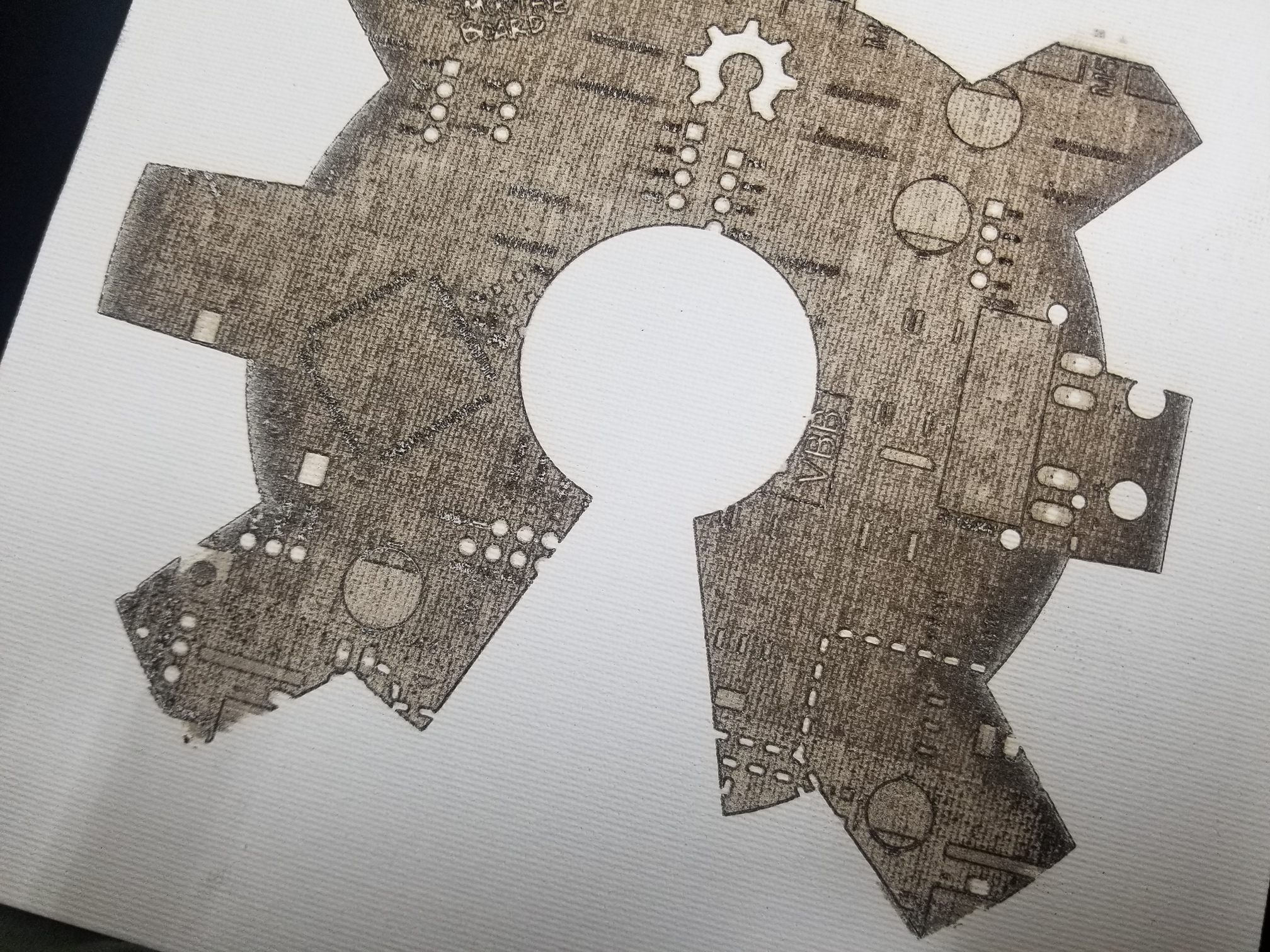
I finally got it mostly working! Thanks for the assistance guys, and for answering my dumb questions. Only issue I have now is how to get it to stop making the edges either too dark or too light.
Hi there,
my name is Wolfgang and I’m from Germany, so please bear with my poor English!
I’ve had a K40 for a year and now want to convert it so that I can use lightburn. I bought the SKR 1.3 with display 12864 and stepper driver TMC2208. The K40 is the one with the digital display. Now I happened to find this topic here where it is exactly what I want to do. The control of the laser with the output for the fan sounds interesting! Can you help me with the implementation?
greetings
wolfgang
Hello Wolfgang,
I would like to help but I have unfortunately grilled my tube to TEM01 mode, so I could never try Squids way to connect everything. Even at the point when I wrote this first post, I already had replaced the mirrors with a diode laser.
I just came back to appreciate what has been going on here. Many people have bought the SKR to try what we explained here.
Good luck to you. I think there will be someone who can help. Else I will try.
Merry Christmas everybody
Yassin
Hi Yassin!
In the meantime I have implemented a firmware with Marlin:
- the stepper motors are running
- the display is running
- the connection to the PC works
What I am missing now is: - which fan pin should be used?
- how does the wiring have to look like?
- how does that have to be programmed in Marlin?
Greetings and happy holidays!
Wolfgang
Hello everybody,
I have now read through every single post and translated it into my language. Now my head is smoking 
I would like to write down my thoughts now:
There are two control inputs
- Fire (on / off) turns the laser on and off
- Power (analog / PWM) controls the power of the tube
With the K40 without change, the power is preset either via a potentiometer or via a digital circuit board and is then constantly applied to the power supply unit. Normally, the M2 Nano Controller only controls the fire via a cable and only switches the laser on and off.
There are three ways the K40 can work after the conversion:
-
As Yassin described at the beginning where you need two lines from the SKR 1.3 (Fire and Power). From my point of view, this is the cleanest solution
-
The Squid solution whereby the power input remains unchanged. The power is set to a fixed maximum with a potentiometer or digital board. The fire input is controlled via a PWM signal, which means that it can not only be switched on and off, but also that the power can be changed between 0 and 100% of the set maximum value.
I assume the MeerK40t software works exactly in this way. With this software, the performance of the original K40 can be changed without any changes! I tested that and had the effect that after a few seconds after the raster engraving the tube had no power when cutting at high power. Then the performance came again. It gave the impression that the tube had to recover first. I have no idea what caused this effect. In any case, that scared me a bit. -
It would certainly also be possible to leave the fire input on constantly and to control the power from 0 to 30% via a PWM input. I think Jawa6988 did it that way?
Is that right for now?
The question for me is now are the solutions 2nd and 3rd for the tube just as harmless as the 1st solution?
Can someone explain to me where the effect I described with MeerK40t comes from?
greetings
wolfgang
That’s not a great choice for a 32-bit controller that can run Smoothieware, especially as there is a specific mode coded in smoothie ware and LB to implement ‘cluster mode’, which significantly improves scanning performance.
The SKR1.3 is a direct copy of the Smoothieboard.
Smoothieware gives you all sorts of features you won’t get running Marlin. Does Marlin handle power correction in corners, now? It didn’t used to. It also didn’t support the 25KHz PWM needed to trigger the K40 variable power control.
I’m not sure why you need a MOSFET-controlled pin for laser PWM. I suspect it’s because of the issue with PWM. I use a standard IO pin and M3/M5 commands.
The biggest deal-breaker, for me, is that you can’t do in-line parameter modifications - you need to change and recompile and upload, vs editing the config file on the SD card and rebooting.
I probably have half a hundred different types of microcontroller on hand, and would never consider anything other than Smoothieware (or GRBL-LPC at a pinch) to run a laser.
Hi bo,
many thanks for your response!
I forgot to write that I am now working with Smoothie firmware. I started with Marlin, but now I work with Smoothieware!
- the board with two TMC2208, lies on my desk and is connected to two motors
- For my tests I put fire (Fan 2.3) and PWM (HE1 2.4) on two PWM outputs with LEDs and can therefore see which output is active when.
- if it is better I can of course switch the outputs to any other output!
- Instead of the LCD12864, I ordered the TFT35, which is due to come this week
- the two motors move and both fire and PWM are activated.
- if I start by hand from Lightburn positions, PWM is active and fire is inactive.
- when I run a program (cut a text) then fire is always active and PWM is switched on when cutting and switched off from one letter to another.
This is the current status
Now to the questions I have at the moment:
- Is the behavior when a program is running, as I have described it, normal? Actually, I had imagined that PWM would always be active and fire would be activated when the letter was cut. Now it’s the other way around.
- Can the behavior be changed to Lightburn (PWM always active and fire switches on and off?)
- (How) can I change the settings of the 2208 via UART in Smoothie? Now I do that with marlin and then plug in the SD with smoothie which is not very elegant!
- Is there a documentation somewhere with all the commands and setting options for Smoothie?
greetings
wolfgang

I know this side of course!
Since the homepage www.smoothieware.org is no longer accessible, all files were simply loaded onto github, but without any structure and the * .html cannot be displayed as such. The documentation is absolutely useless and pointless!
Or can you download all the files and then have a functioning documentation on the PC ???
To get the doku i have downloade the complete https://github.com/Smoothieware/Webif-pack to the PC!
Now I’ll see if I can get on with it!
My apologies, I didn’t realise it was going to be such a hassle. They used to have a great wiki that contained all the docs.
I’m sure I’ve seen a way to execute the raw html…
EDIT: Of course you can: http://smoothieware.github.io/Webif-pack/
And the docs: http://smoothieware.github.io/Webif-pack/documentation/web/html/index.html
Try that.
It’s a matter of adressing the actual file, rather than the GitHub interface to get to the file source code.
Yes, there are two ways:
- via the link you have given or
- Copy the entire Wiki to the PC and then open the index.html.
Another question cleared up!
Now it is about the configuration of TMC2208. I only found minimal information in the wiki.
Actually, you can only set for each axis with the config.txt:
alpha_step_pin,
alpha_dir_pin,
alpha_en_pin,
alpha_current,
alpha_max_rate
The board is set to UART but I have the impression that nothing changes in the current when I change the values in the config.txt. Many things like step resolution or holding current cannot be changed with it. How should you use the 2208 with the SKR V1.3 and Smoothieware and how can you completely configure it?
I realize that this has nothing to do with Lightburn but is a topic for smoothie goods or hardware in general, but maybe there is information about it here!
Should you proceed according to these instructions or is there an easier way:
https://learn.watterott.com/de/silentstepstick/configurator/
The SKR V1.3 is connected to the small adapter board for the ribbon cable. Today I wanted to do the first test. Now it’s about the connection of the SKR with the laser PSU. In the meantime I have read a lot about how the board should be connected to the PSU in many forums and also here.
To be on the safe side, I also looked up the Smoothiewaredoku again and found that:
“Wiring
In order to control the power of the laser tube, the laser PSU reads a PWM signal as it’s input.
Please look at the datasheet for your PSU to know which connection that signal is wired to.
From the Smoothieboard, you need to connect :
One GND pin to the Ground connection on the PSU
One of Smoothie’s PWM pins to the PWM input on the PSU”
So they only connect one cable, namely the PWM signal with the PSU!
The PSU has two inputs:
L = switches the laser on and off
In = controls the power of the laser
If the PWM is clamped from the board to the In of the PSU, L would have to be constantly set to 0 (laser is always on) so that the power could be controlled from 0 to 100% and thus also activated or deactivated.
If the PWM from the board is clamped to the L of the PSU, the laser power must be set to a fixed value with a potentiometer connected to in, so you can no longer change the power via the software, right?
Or is it meant that with the PWM from the board you can switch the L from the PSU on and off so quickly that the power can then be changed?
I believe this is the most frequently asked and discussed question when upgrading!
I have now installed the SKR 1.3 and carried out the first test.
With PWM from the board just like that on L of the PSU it definitely doesn’t work as desired! Maybe there are different PSUs, but with a power supply unit that has L and IN it doesn’t work that way!
The cutting works, but as soon as you can fill an area, you notice that the tube starts to fire on one side with a certain time lag and then something is missing. As a test object I drew a small rectangle in Lightburn and then cut it or had it filled in. The faster the X-axis is moved, the smaller the filled area!
I am now converting it to an output for L and a PWM output to IN of the PSU.
Now I need a simple circuit to connect a PWM signal 0 to 5V from the SKR V1.3 to the PSU.
Is there no PWM pin that delivers 5V? If not, I had already considered pulling the fan output to 5V. If the fan output then switches to GND, you have the range between 0 and 5V without an additional board!
Edit: It just occurred to me that you don’t have a 5V! 3.3V are sufficient because you never need 100% with the CO2 laser. 3.3V are over 60% of 5V and I am currently working with 30% = 12mA. The 3.3V signal should be able to be connected directly to the IN input of the PSU without an additional board! Or am I making a mistake?
Your original post told you - gnd to psu gnd, pwm output from smoothie to IN
You are significantly overthinking/over-complicating this.
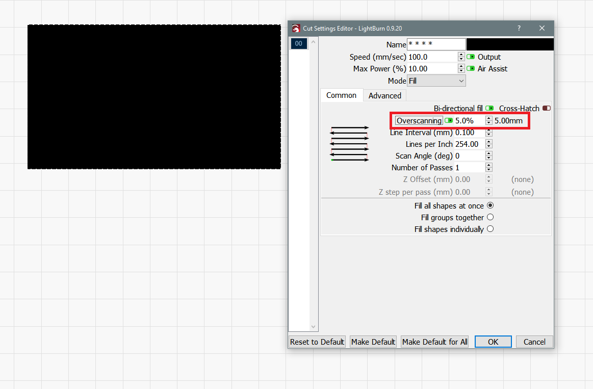
I can’t visual your scan issue cause you did not share a picture but have you tried overscanning?
https://lightburnsoftware.github.io/NewDocs/CutSettings-Fill.html#overscanning
My laser is now working as expected!
I’m in the process of engraving faces in plywood which works just fine! I laid three cables from the SKR V1.3:
GND board to GND PSU
Fire Board to L PSU
PWM board to IN PSU
By the way, you don’t need a conversion from 3.3Board to 5V PSU because you shouldn’t get 100% power from the tube anyway.
If I put 60% power in Lightburn then I have about 12mA on the current display. Simply connecting the PWM board to the L PSU is basically possible, but you still have to manually set the respective good maximum current on the potentiometer. The setting via PWM is then not very finely feasible compared to wiring now with both connections L and IN to the board.
Also PWM board to IN PSU and GND board to gnd PSU cannot work because the laser does not fire as long as L is on +! In order for the laser to fire, L must be placed on gnd. You could of course connect L PSU to GND, but then the laser is always sharp and you can no longer trigger it with the test button!
Congratulations
You should work out what pwm setting corresponds to the maximum mA you want to achieve and set that as the upper limit in smoothieware
That way you can never accidentally overdrive your tube
In the next step I will test Marlin as firmware. Smoothie does not support TMC2208 via UART! This means that the currents, the step resolution and so on cannot be changed on the board. The 12864 display worked immediately with Marlin, but not so far with Smoothie. There’s a lot more support for marlin than for smoothie. I’ve also talked to the developer of Smoothie. He seems to be very inflexible and not very open to additional options that are not available on his own board! In my previous tests with Smoothieware, I also had an interruption on an engraving project. I can’t say whether that was due to the firmware or something else, but the interruption definitely occurred.
C’mon man, I run SKR1.3, TMC2208’s, BTT’s TFT35 and Smoothie Cluster.
My Advice for you is to Think twice before switching to Marlin. you might lose more than you will gain. Who needs UART if you can set things once and forget about them? I edit my smoothie’s config file directly from Lighburn’s console. easy.
Since I switched to the Cluster flavor and updated to 0.9.20, all my engraving issues went away. no more connection issues, no more stuttering before rasterizing starts. i might get those at a later stage (you can’t trust machines too much) but so far - so good.
Cheers 
1 Like