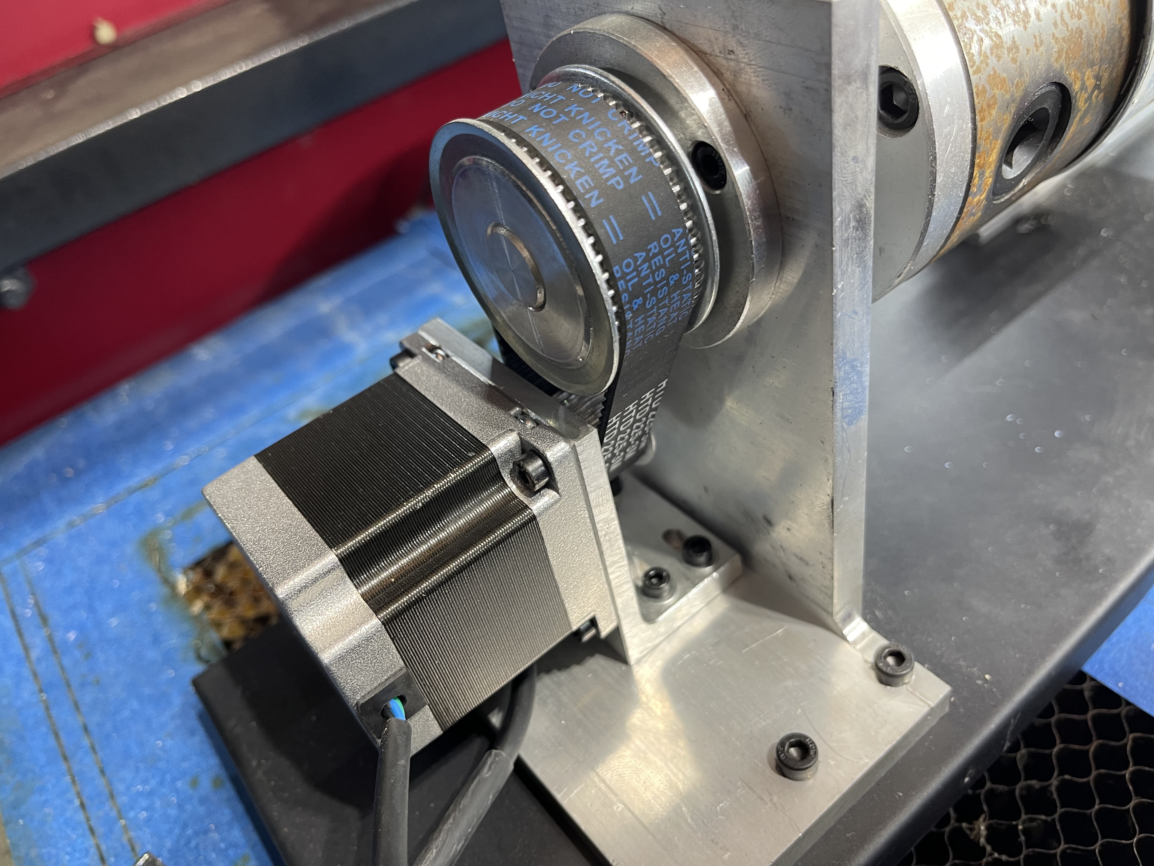
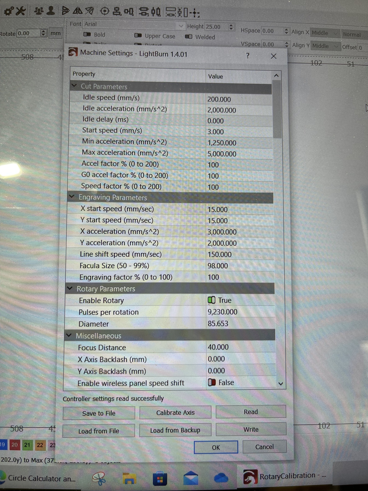
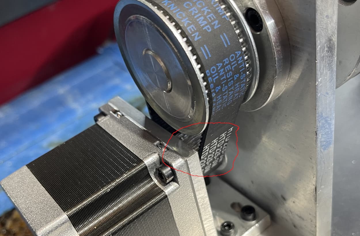
I have a Chuck Rotary from OMTech. Red and Black 60W OMTech Laser. I have read many posts and saw one that was very similar to my issue. I went as far as counting the teeth on the motor to find the ratio.48 and 26, 9230 Steps per rotation.
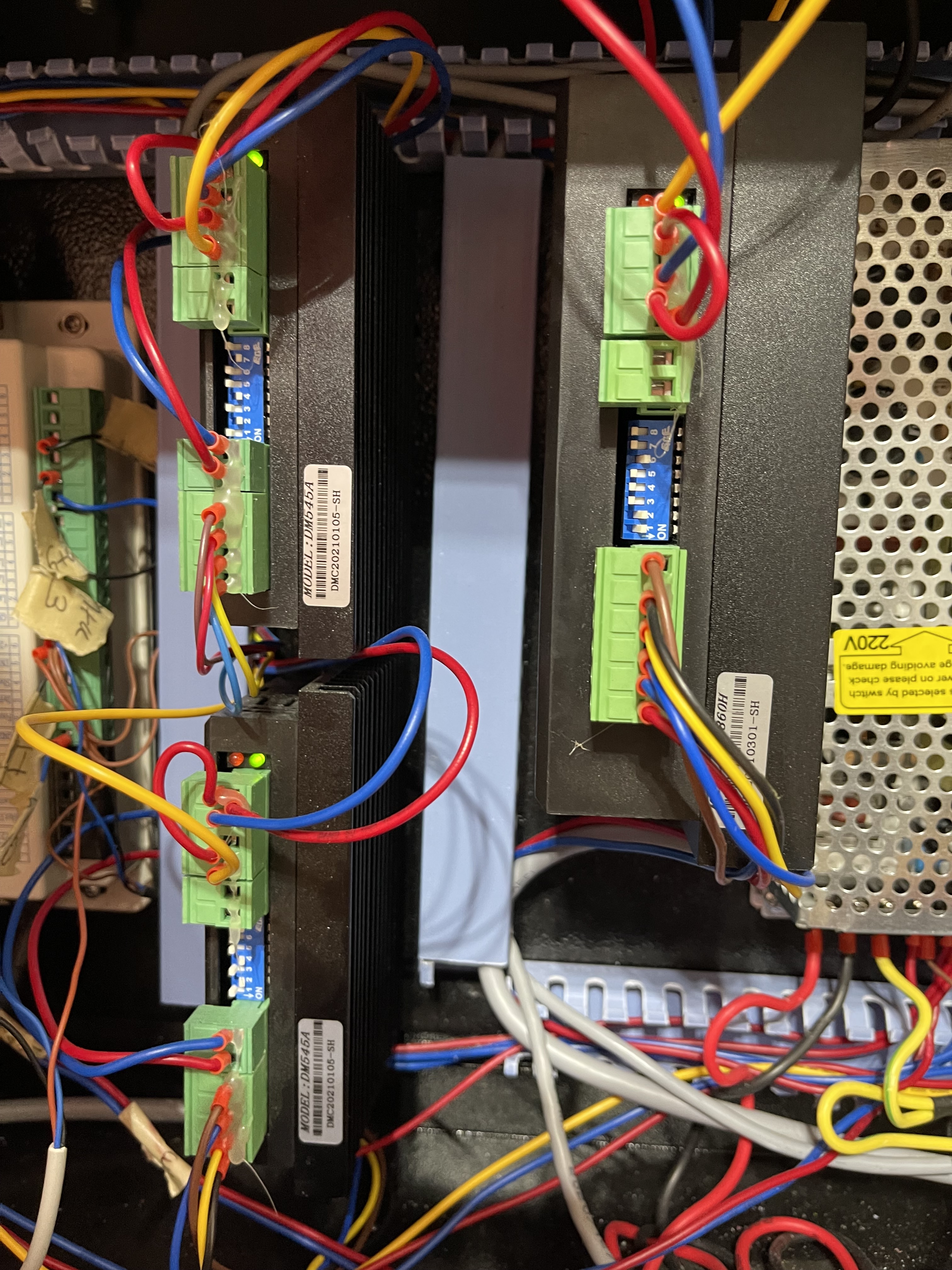
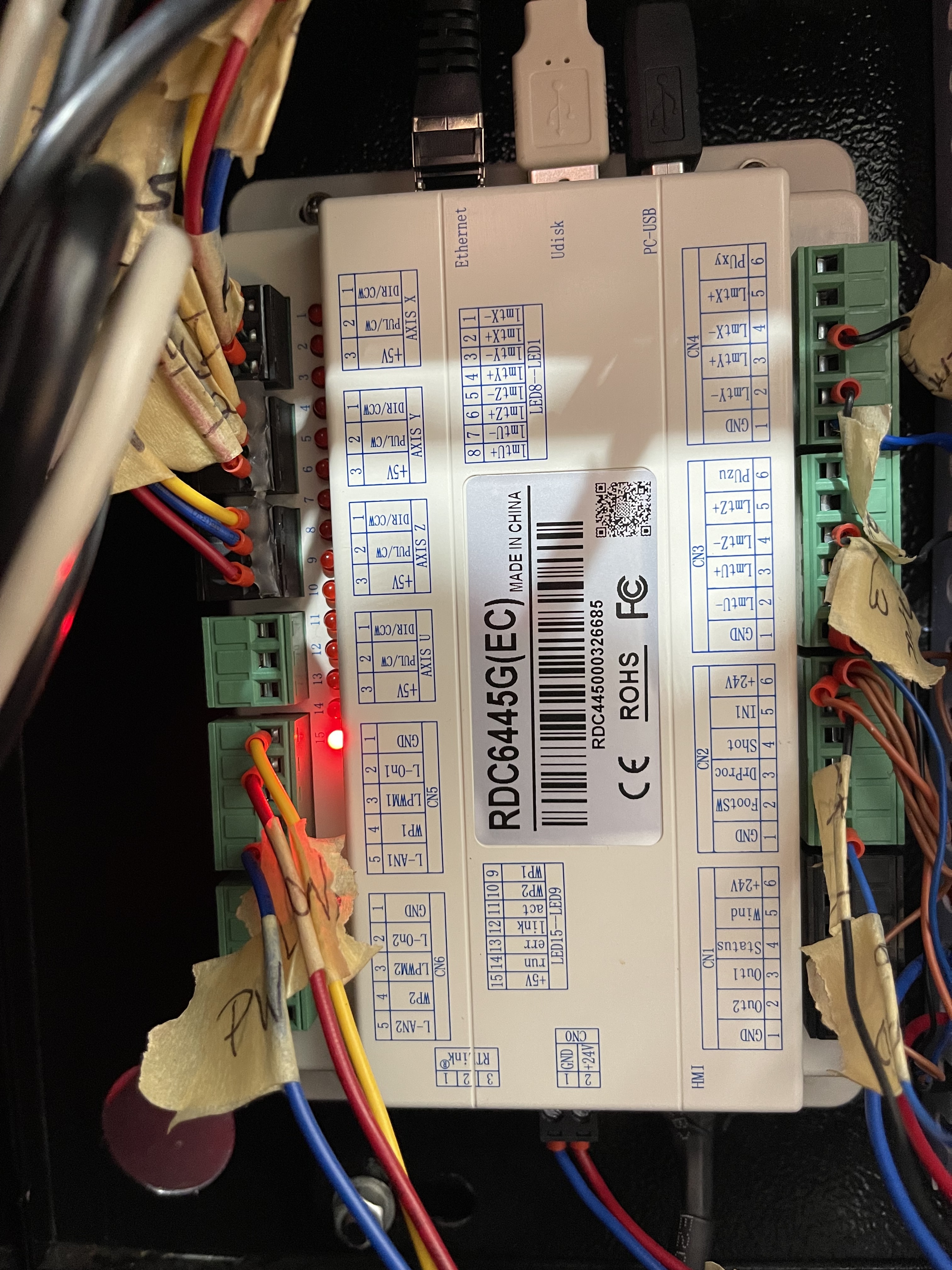
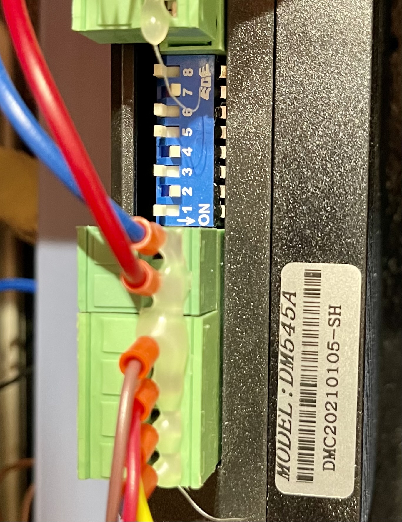
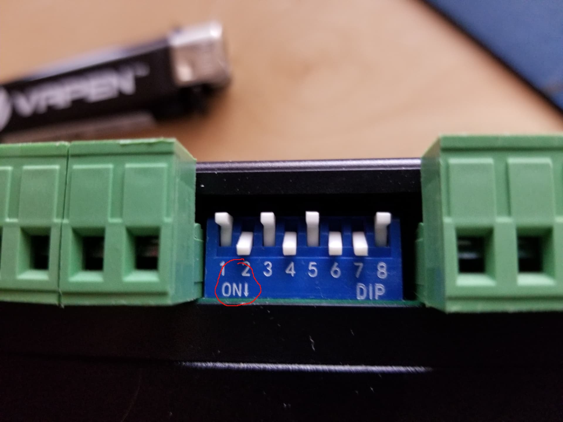
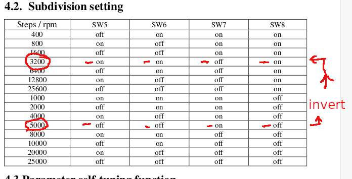
I have checked the stepper motor for the Y axis, It is 5000. I have the DM545A. My manual says the Pulse/Rev default is 4000. I replaced the original controller and have the Ruida RDC6445G. The dip switches on my motor indicate 5000, 2, 4 and 7 are ON.
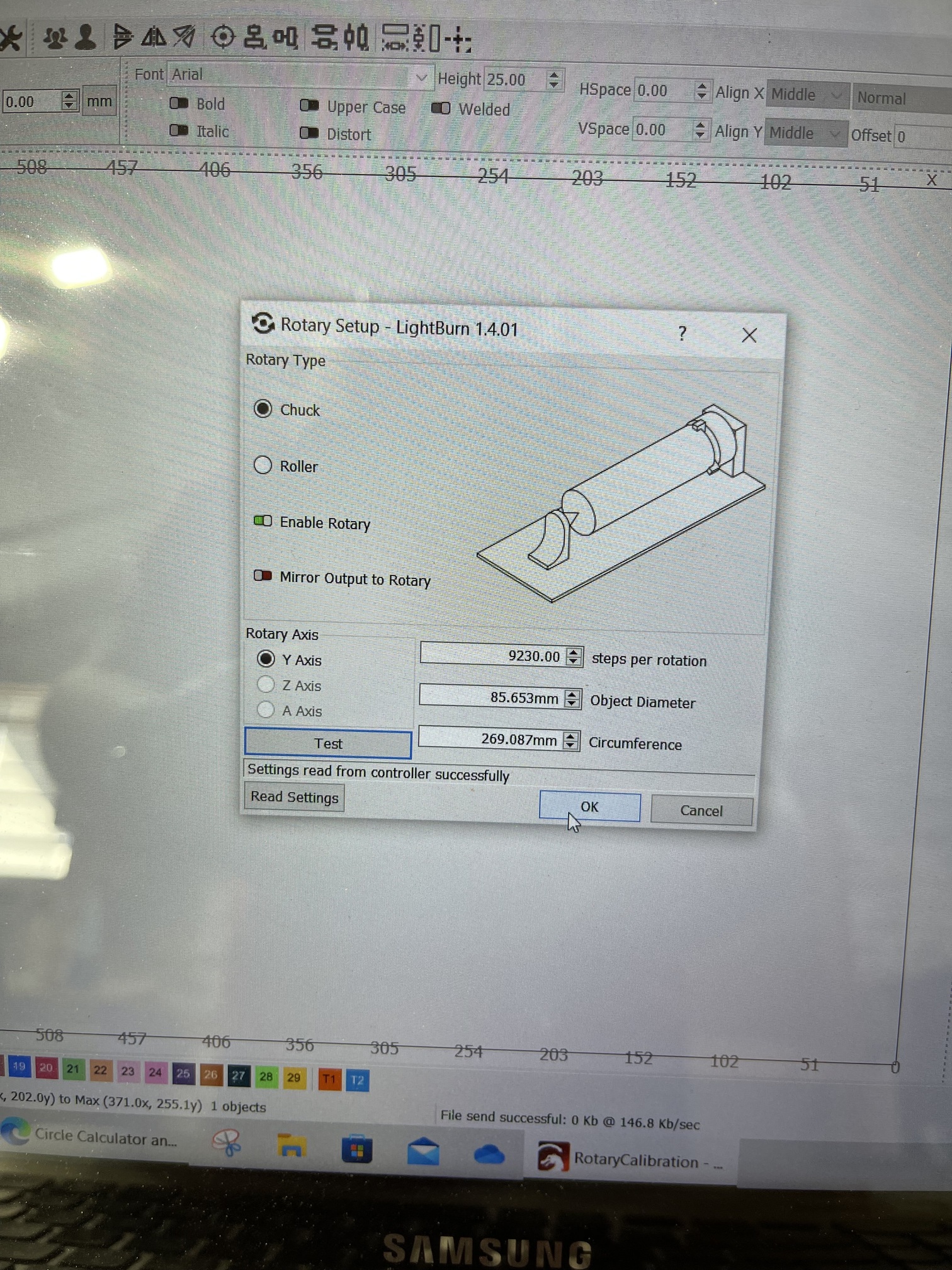
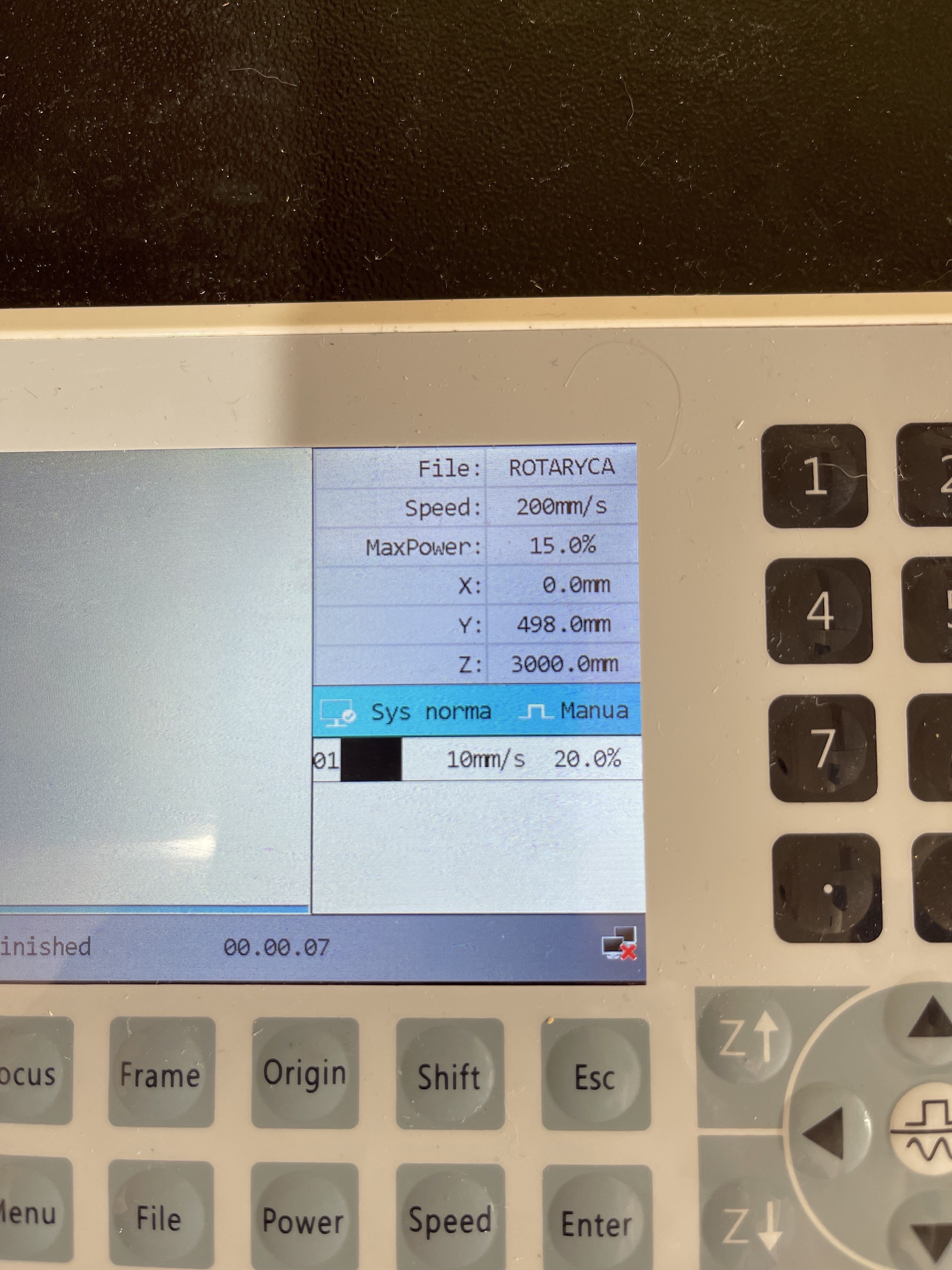
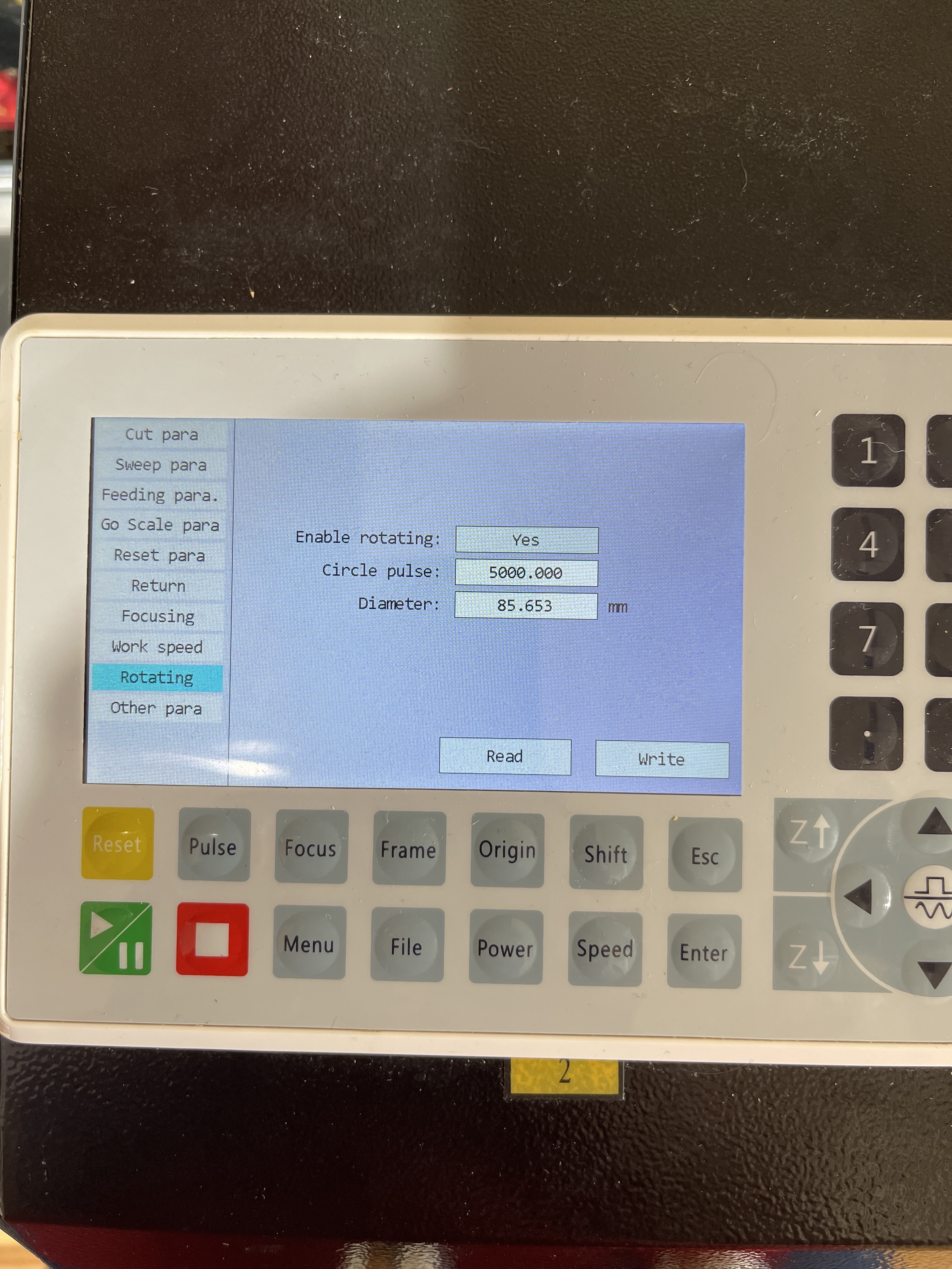
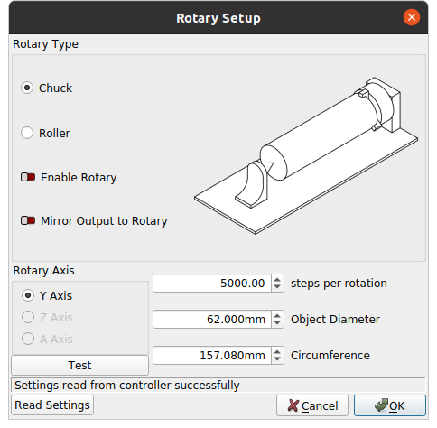
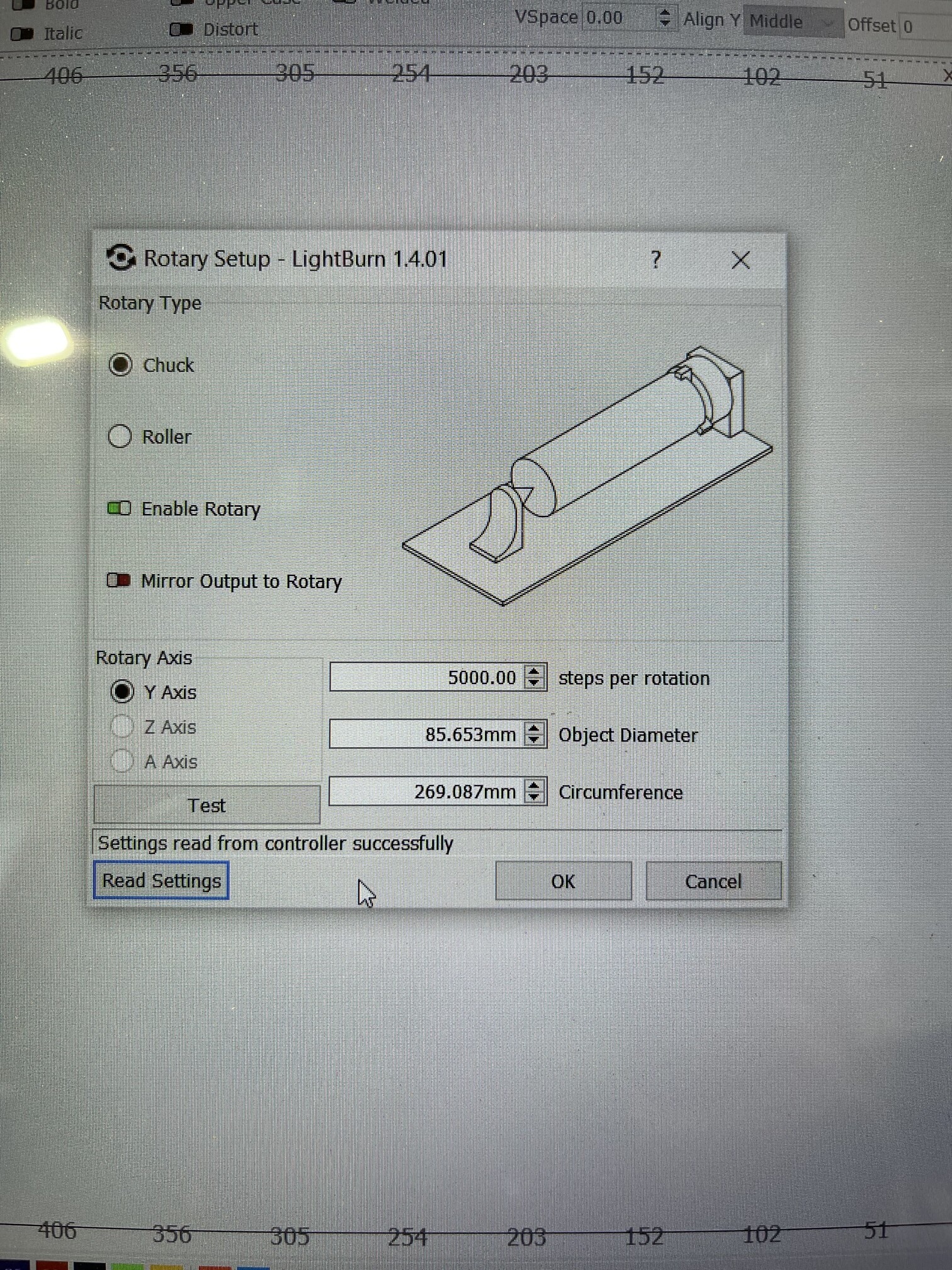
I do the TEST in the rotary set up and it rotates 2.25 times. I can get to rotate just once by changing the diameter - which should NOT be a factor. If I send a job, the rotary does not move.
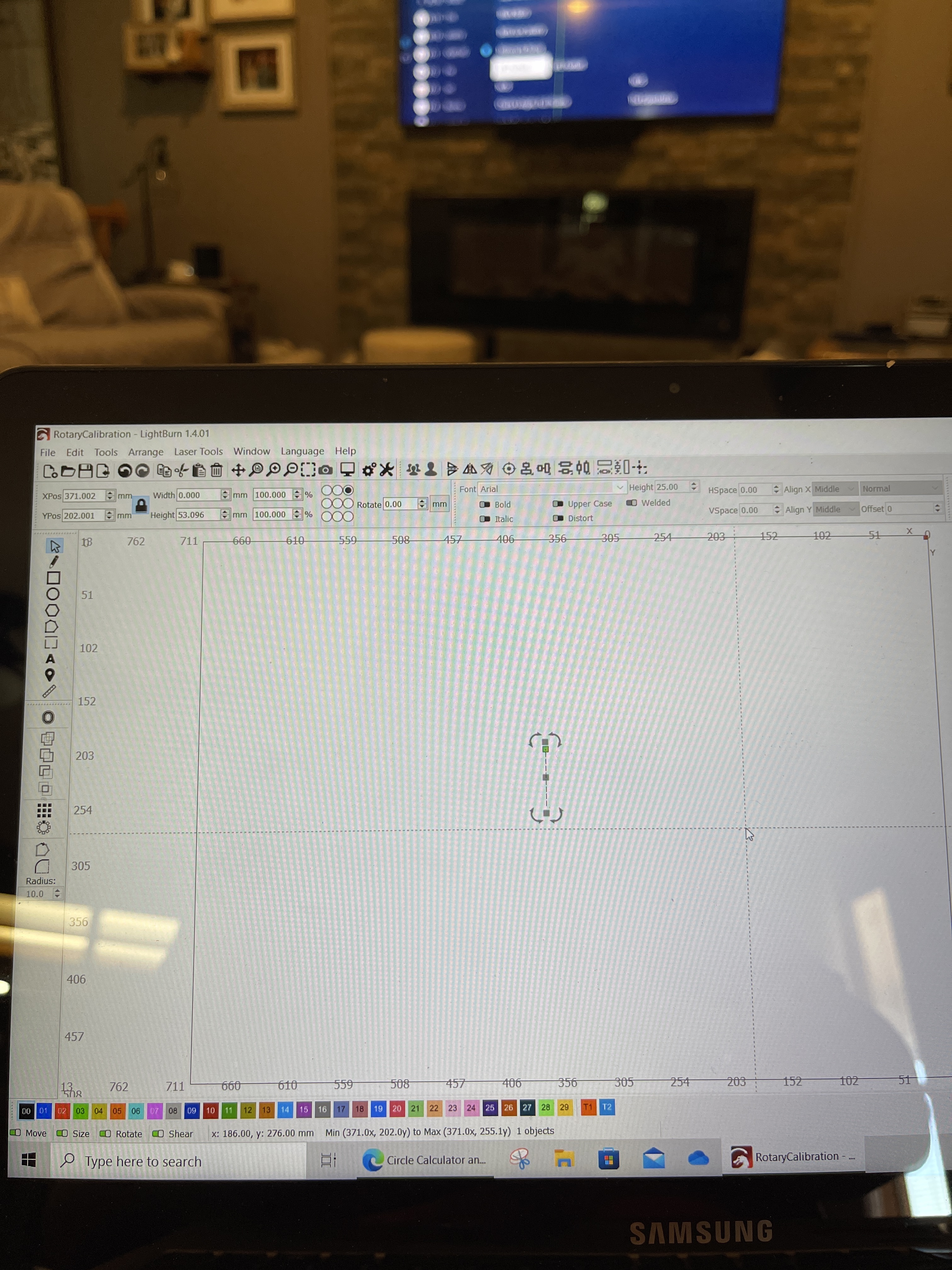
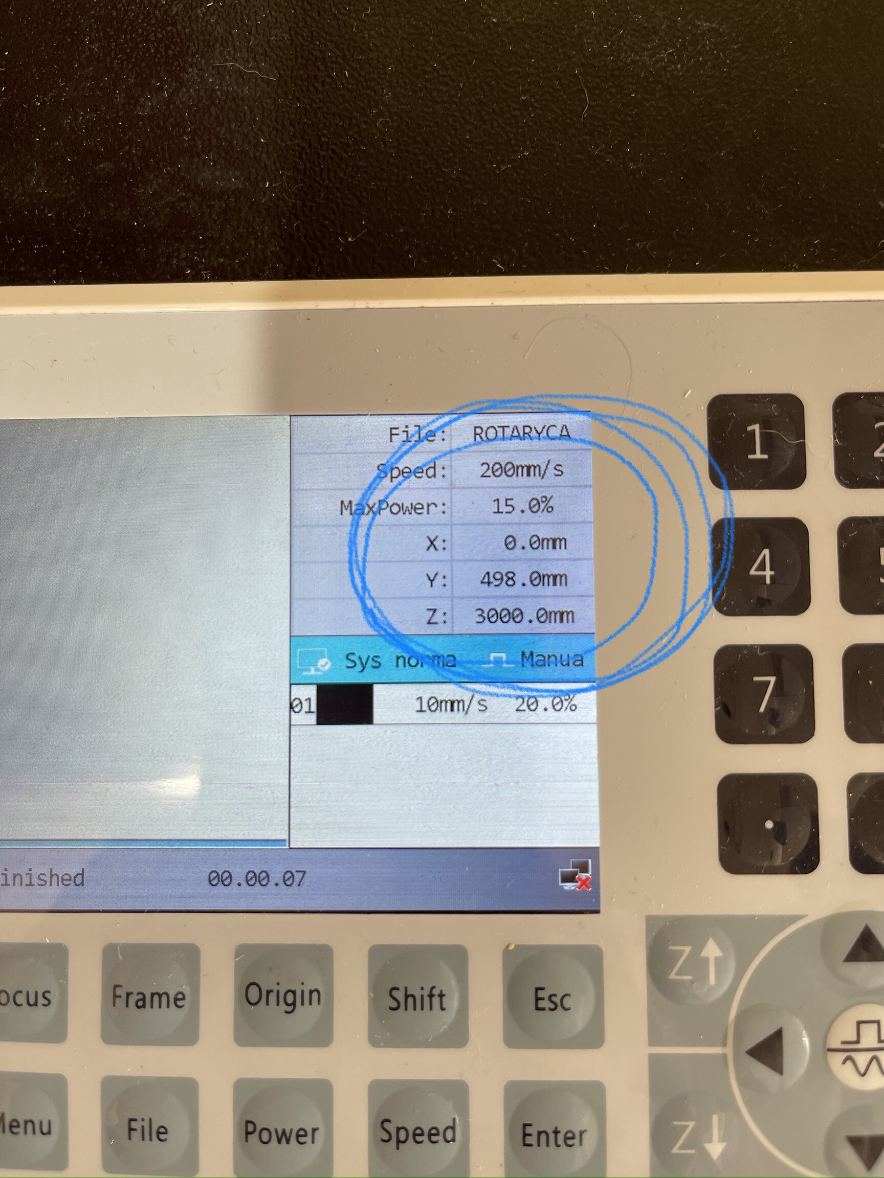
I have done set up: send file to Laser (use current position), align the X where you want it and manually the Y, Press “Origin”, then play. The numbers for the Y axis on the controller show it moving the distance of the line I have sent to engrave; BUT, it does not move at all. See videos.
There doesn’t seem to be any artwork on your machine console? What is the art you are trying to put on the rotary?
It sound like you have the basic requirements set…
Try this… if the motor driver is set to 5000 steps/rotation, you can set that value in the rotary gui for steps/rotation and watch the motor… the motor should rotate one rotation and back… with the gui test button.
If that works it’s your ratio between motor and chuck. If you can’t get the motor to operate one turn and back it’s not going to work at all…
Stick a piece of tape or something on it in a way it won’t interfere with the belts or anything so you can tell if it’s working correctly.
I am not sure how to tell the difference. The rotary has a motor. It is plugged into the Y? The rotary chuck rotated, I am not sure if the Y stepping motor was engaged? How do I trouble shoot it?
gotcha. I put a small piece of tape on the belt. It rotated 1.5X.
I am only allowed to make so many posts in a day. So I am trying to edit one to answer your last question. Just verified the switches. 2,4 and 7, is what I see. Am I reading it correctly?
Following along Madam Tinker
Agree with your math although visually the pulleys look like a bigger difference.
Agree 5678 off off on off = 5000 and your photo looks correct
Agree changing the diameter should not affect the 360 rotation when you hit test.
It would be more simple to just enter the 3200 steps/rotation in Lightburn and watch the motor pulley…
Probably more simple than crawling around trying to read the configuration switches.
It always annoys me, with all the technical data they give you, motor phase, torque etc… with these rotaries, but leave out the gear ratio… Something simple for them and a pain for the user.
I agree with the annoyance…
EZ has a ratio field, why don’t we… Anyway, looks like the crawling around has already been done if the photo was the correct microstep driver. What is a reoccurring theme is the revs seem to change based on diameter, which it shouldn’t whether the ratio was correct or not. Similar to the other posts mentioned. Something else is going on, way over my head. Just following along for the education.