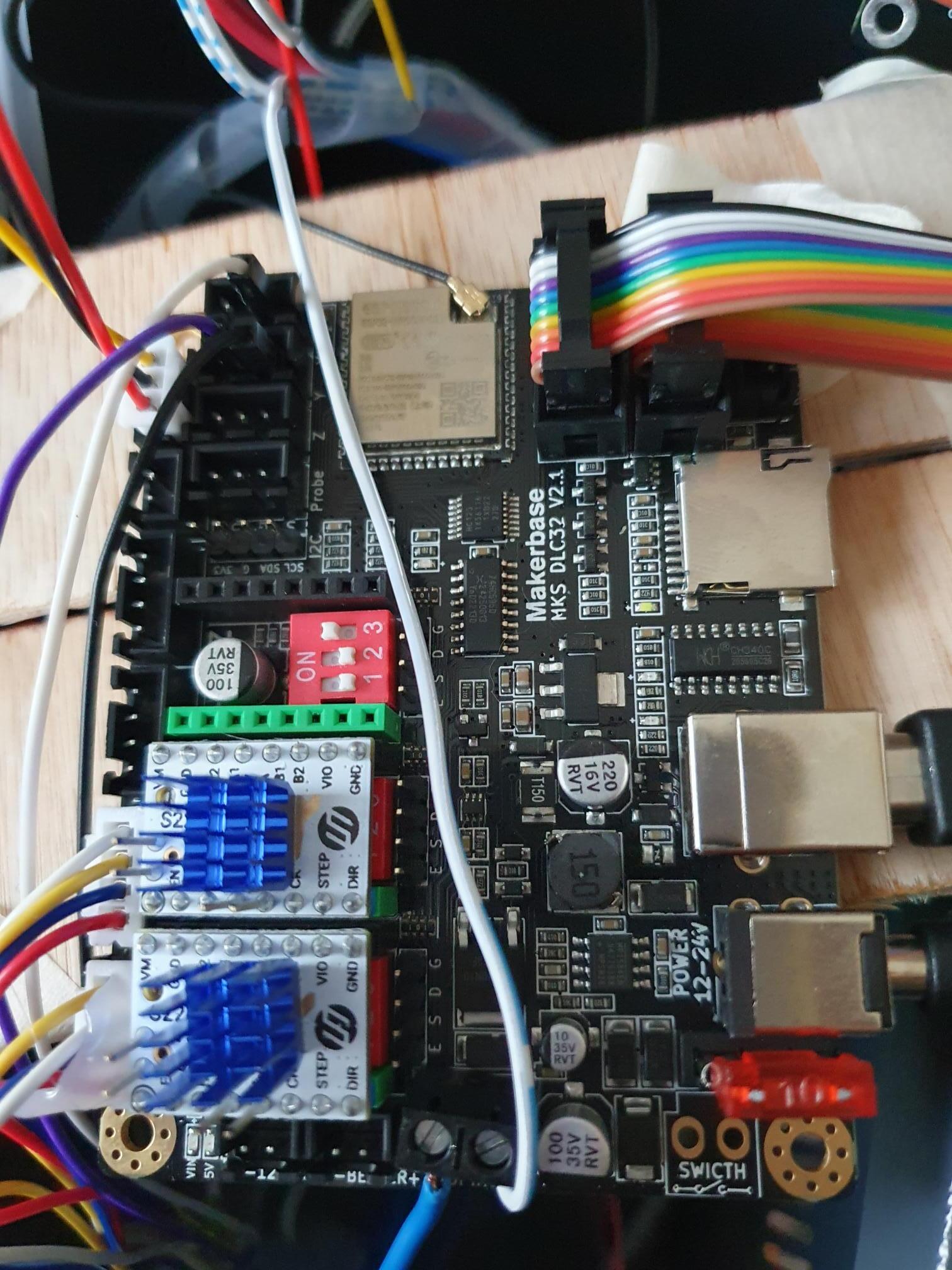
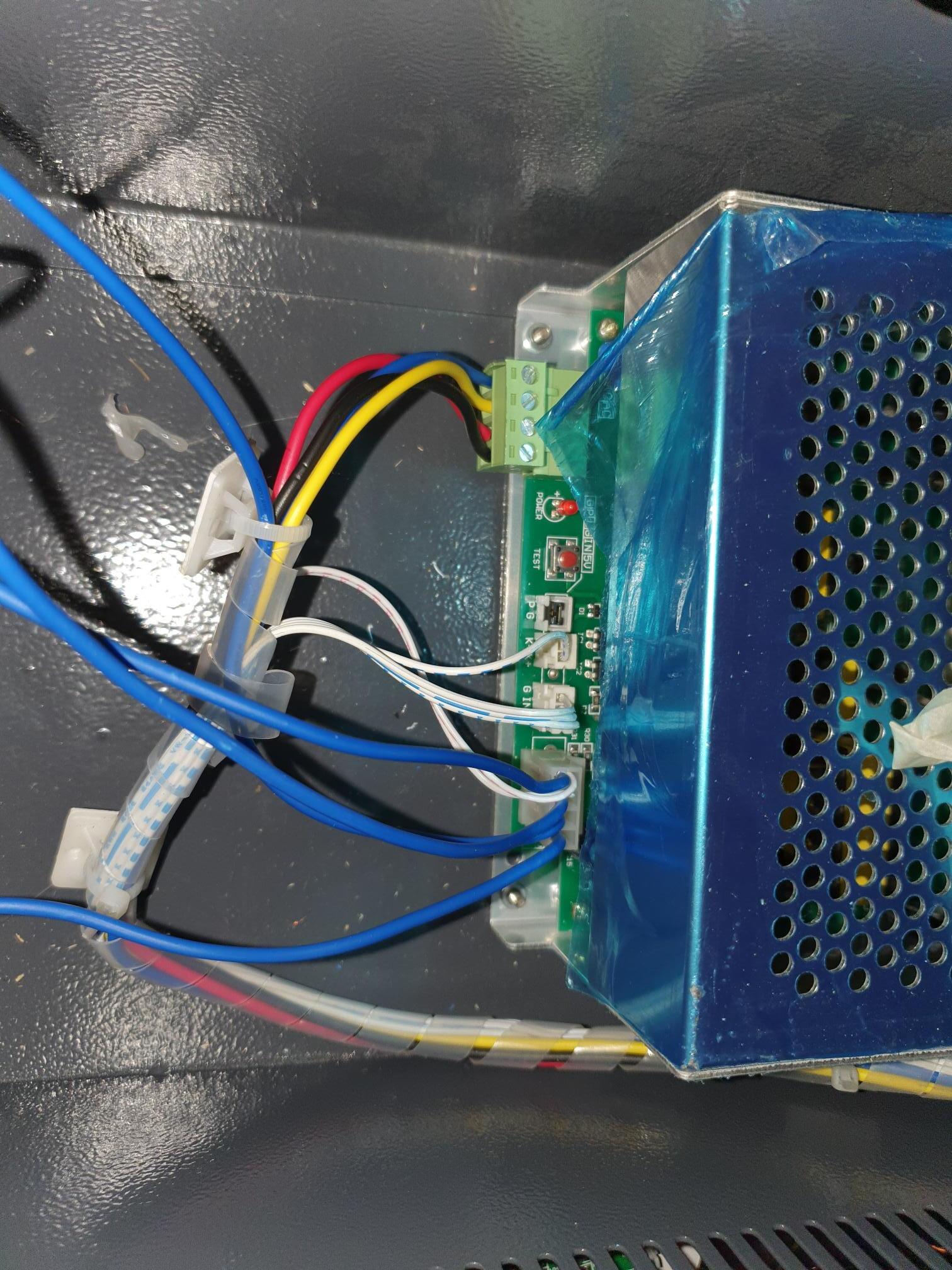
I am looking for some help as looking through youtube videos, various forums including lightburn and the Makerbase documentation regarding the MKS DLC32 V2.1 I am confused on where the wiring should go the the K40 laser engraver.
So the where the blue heatsinks are this is the stepper motors these are working fine. The purple and black wire and the white above them (should be another one) theses are for the limit switches
When I press the switches I get the following error
The first issue is the limit switches when homing they do not register hitting the limit switches and bang against them. I’m not sure if this is because of limit switches not in the correct place on the motherboard currently on G and S (do they need any current as only 2 wires go to the switches) or if
the gcode is wrong, Which I have included
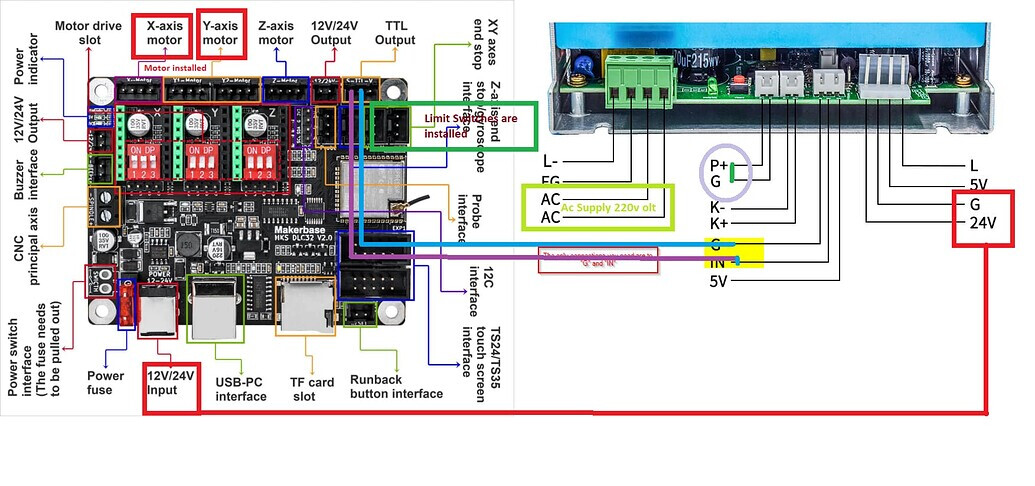
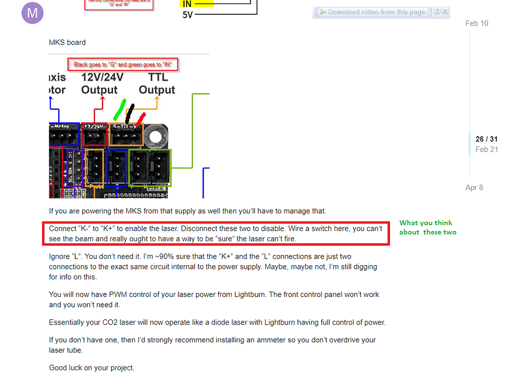
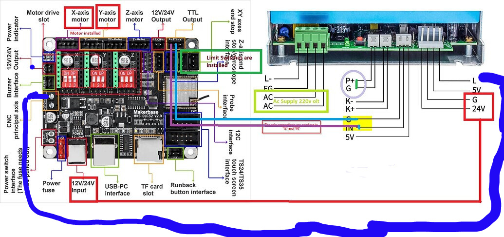
The next issue is trying to figure out where the wires go for the laser to be fire when the command is sent again this could be an error in the gcode above. If i have understood the $32 set to true should enable it? I have looked at MKS DLC 32 with K40 - #38 by Atif but it is not clear where the laser wires should be. I have connected k+ and k- together connect L to the spindle negative and IN on the psu to positive on the spindle on the motherboard
I will create some documentation for the group when this issues have been resolved as this may help someone else in the future
Let me clarify a few things, just to check my understanding as looking at various forums, you tube videos etc… I totally confused.
From my understanding
I have removed the short of the K & K+
The limit switches are working correctly by the error given in lightburn, I need to figure out why the head keeps bashing against them and does not stop (Any idea there would be helpful)
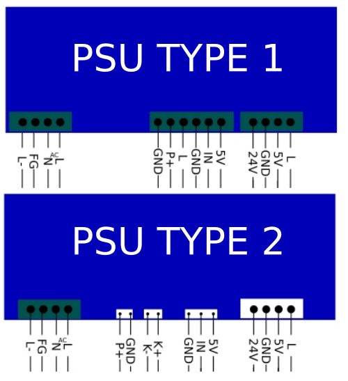
For the laser we need L- and the IN wires from the psu going to the Makerbase MKS DLC32 V.2.1 board, Looking at the documentation then IN goes to S on their documentation and L- goes to G
I don’t have one of these, so this lps is different from what I’m used to. I am following the previous link… it wouldn’t hurt to get assistance from @HalfNormal
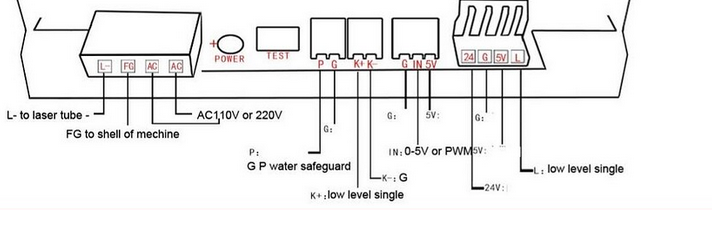
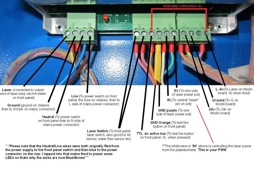
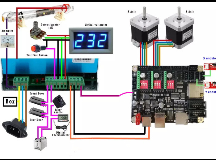
Take some time and read this. These are the lps connections…
Connector #1
Pin #1 HIGH VOLTAGE Return (from ma meter)
That goes to the cathode of the laser tube… generally you put your mA meter in this return line.
The link has a guide for the IN, G and 5V connections…
Pin #1 (G) – Pot CCW Pin (turning knob ccw contacts this)
Pin #2 (IN) – 0-5V level control to High Voltage Power Supply
Pin #3 (5V) – Pot CW Pin (turning knob cw contacts this)
Your documentation is for an led laser, how they are wired is a bit different as you can control the power in two ways, via the external pot and the software percentage power.
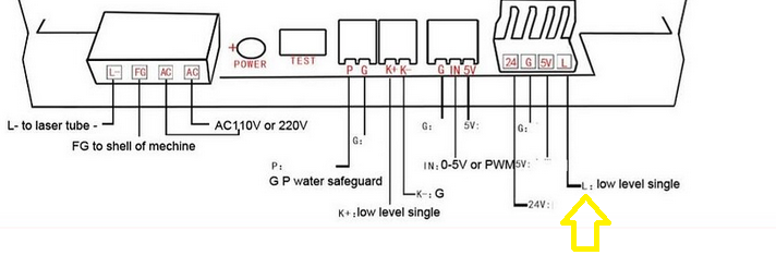
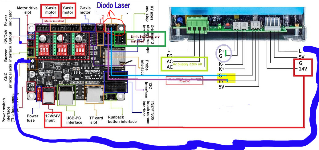
This is the only place that seems to fire the laser and is probably where your S signal should go… This is just the pwm requested by the artwork layer. It appears to be active low.
I thought I’d taken a photo but can’t have done and I just need to find with the L wire connects to as I left it connected to the connector on the psu but not sure where it connect to?
In regards to the controlling the laser, I was looking to do this within lightburn software via percentage power whether this is for a test fire and engraving/cutting. so does this change anything
Now since my display is digital for the laser power
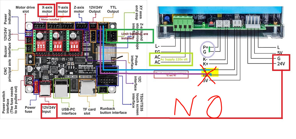
Pin 1 from the psu goes to Ground on the makerbase motherboard
Pin 2 from the psu goes to Signal on the makerbase motherboard
Pin 3 from the psu goes to Volt on the makerbase motherboard
going by
Pin #1 (G) – Pot CCW Pin (turning knob ccw contacts this)
Pin #2 (IN) – 0-5V level control to High Voltage Power Supply
Pin #3 (5V) – Pot CW Pin (turning knob cw contacts this)
Atif replied as i am remembering/recalling of memory about my failure is when i press fire on LightBurn and connect K- and K+ pin laser tube fire up.
But when i gave some sketch to draw the laser tube did not fire up because i did not connect of short K- & K+ pin
Atif then mentioned it is correct we need to short K- & K+ in MKS DLC 32 V2.1.
Now laser tube is firing up and working…
So my interpretation of this is Black from TTL on the Makerbase motherboard goes to ground on the psu next to IN. The green from S on the Makerbase motherboard goes to go IN on PSU.
If this work by connect and disconnecting the K and K+ one will go as test fire on the circuit and the laser when running a job.