Hi John J
how is the acquisition of the new board progressing.
Trevor
This topic was automatically closed 30 days after the last reply. New replies are no longer allowed.
Hi John John “You said Smoothie is a new process for me and I’ll be ordering a C3D board right away”
Have you received the this board, and if so will u be posting, regarding the non alignment of cutting layers.
Regards Trevor Boundy
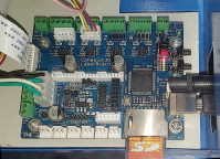
The board is here and I pulled the config.txt file off the card.
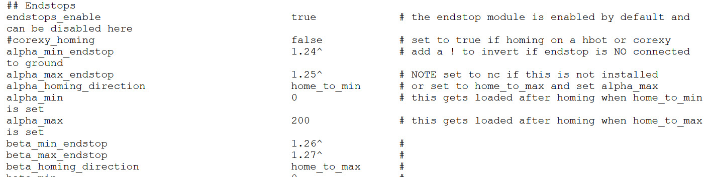
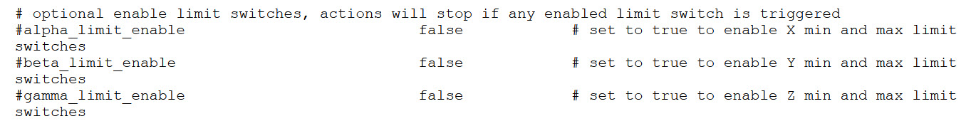
The most glaring thing for me is a distinction between the Endstop switches which are enabled and the limit switches are not active by default.
I have to grab a couple of things for a project / testing but i’ll hook the board up and attempt to talk to it tonight.
Tar. John
Just as a check for u, here is my config.txt file from my usb card
config.txt (28.4 KB)
Trevor
1 Like
Hi John Johnson
Are still available to help me with my Cohesion3D displaced images problems ?
Happy New Year. John ![]()
Kind regards Trevor Boundy
Hi John Johnson
Are still available to help me with my Cohesion3D displaced images problems ?
Kind regards Trevor Boundy
Hi John Johnson
Are still available to help me with my Cohesion3D displaced images problems ?
Kind regards Trevor Boundy
This one got past me. My apologies for the delay.
If you select the reply button near my posts I will receive a notification when you respond.
This still appears to be a lost motion behavior where the head hits the limit and the motion steps are counted and the head can’t move. When the head comes off the limit, the real location and the ‘believed’ location are different.
I looked in the Config file and didn’t see axis length settings. It may be gathering this information from the switches. Have you installed all 6 switches?
I just found a resource that mentions that on some units the Y axis can hit the exhaust vent inside the K40. When the exhaust vent is removed the full length of the Y axis is available. With the exhaust vent installed inside the machine the Maximum travel is closer to 150mm.
If the gantry is colliding with the exhaust vent and preventing the limit switch from tripping that could be all there is to it.
With the power off, please confirm that the gantry (Y-axis) can move freely to both ends of the 200mm limit. You may want to reduce the Y-axis value of the work area to 180mm or less depending on what is available when the limit or end stop switches release.
1 Like
Thanks John,
6 switches ?
Y axis one limit sw, supported by ribbon cable to Cohesion3D
X axis one limit SW, supported by wired cable to Cohesion3D
I chopped the exhaust vent on first receiving the M/C.
With power off he physical Y travel measures 230mm.
Powered up, using Lightburn Home to Origin Y travel measures 200mm
Trevor
Hi Tim (MrMag)
I still have no reply from John John.
Do u think i should mark him as resolved, and re-start the topic again?
How do i get a general blog response?
I’m at a bit of a loss as to what to do Next.
Your advice appreciated Trevor
Please select the reply button next to my response so I receive a notification.
Even bettter, please use @JohnJohn so I don’t miss another response.
Good stuff!
With the project loaded up select Ctrl-shift-A
Then capture the screen in the same way you did above.
then Ctrl-shift-0 (control shift zero)
Then capture again.
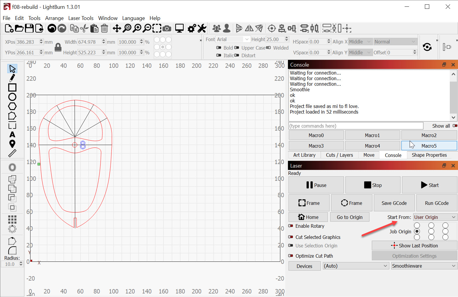
I would like to see the workspace settings and if LightBurn is attempting to engrave outside or work outside what is allowed for your engraver.
LightBurn Home? This may be a user origin that you have set. Please capture the screen with the Laser window visible so we can compare.
I downloaded your config file and I see 200 x 200 as your work area.
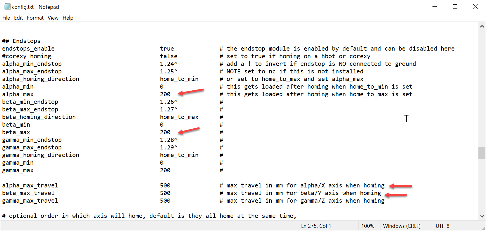
Adjusting your x-axis in the config file to 250mm and turning off the absent endstop switches may be all that’s missing.
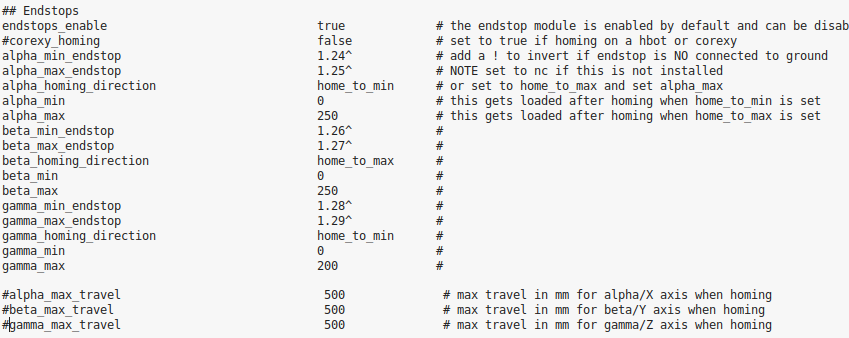
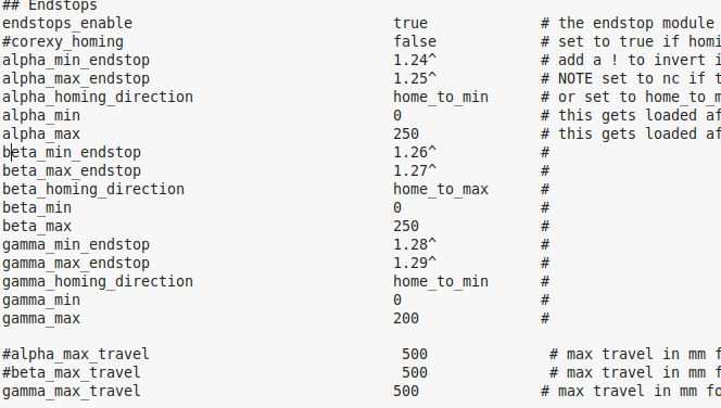
X is alpha, it’s homing to minimum so the switch is at x=0.
alpha_max_endstop should be set to nc instead of 1.25^
alpha_max will be set to 200 (again, suggesting 250 or more)
Y is beta, it’s homing to maximum so the switch is at y=200
beta_min_endstop should be set to nc instead of 1.26^
beta_min will be set to 0 (zero)
x_min (0) and y_max (200mm)are the correct placement for the switches:
We’re expecting the engraver home toward both switches in the back Left hand corner on start-up.
If the switches trip before the physical limit of the engraver the X will be set for 0 (Zero) and Y will be set for 200mm. If the Y max switch trips at 180 the engraver will attempt to go to -20 instead of zero. If the Y max switch trips at 220mm, Y will stop won’t go below 20mm.
Do you have a z-axis motor?
The alpha_max_travel, beta_max_travel and gamma_max_travel at the bottom of the capture should be left at 500mm That’s how far the engraver would be willing to go to get to the switch. These are ok.
Don’t give up on John John, You just need to post a new message here for him to see. He will answer you, I am sure of it. LightBurn support is the best I’ve seen.
1 Like
OK John got yours, i think the think u were going to do receive a Cohesion 3d board to test one of my plywood former’s
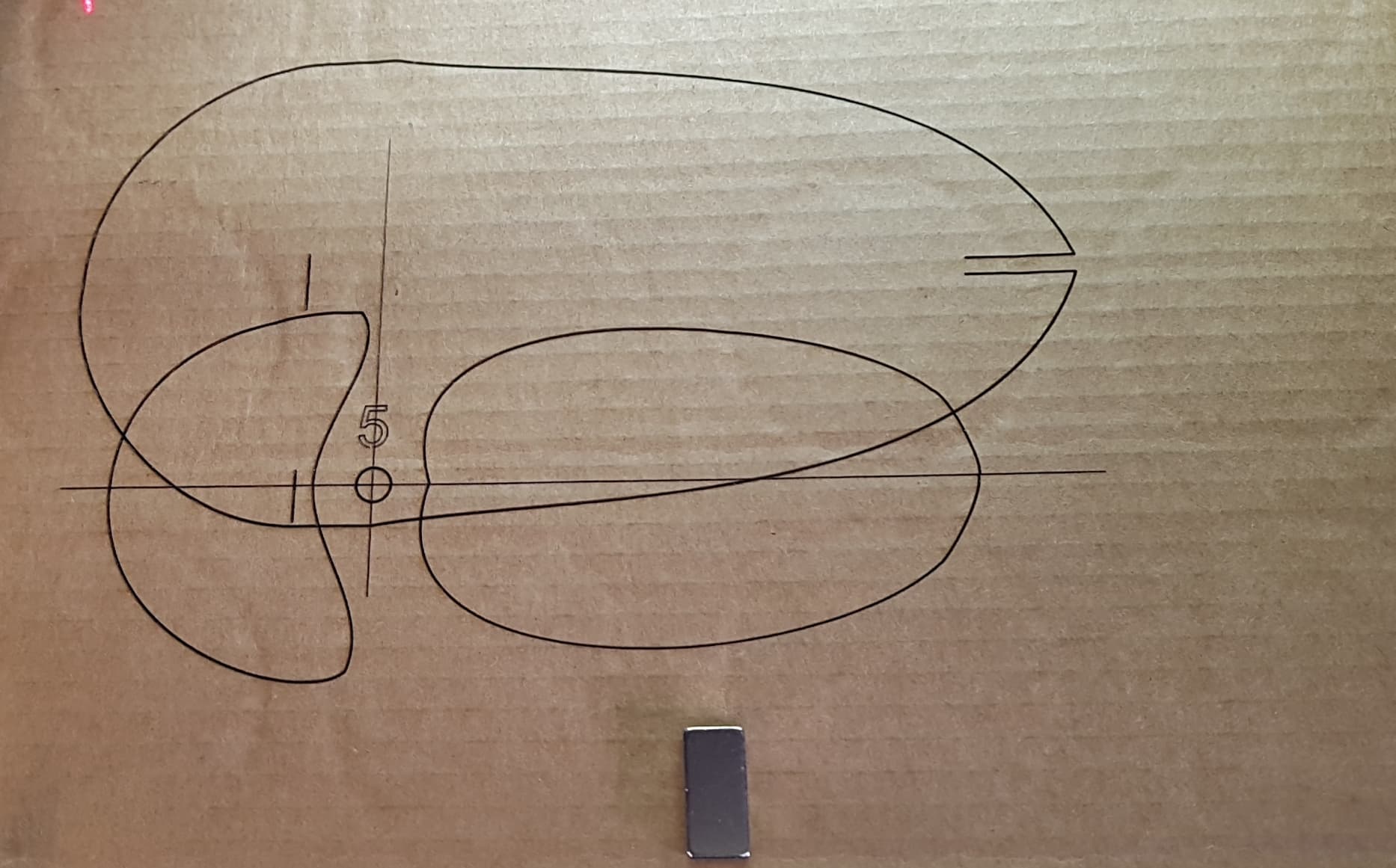
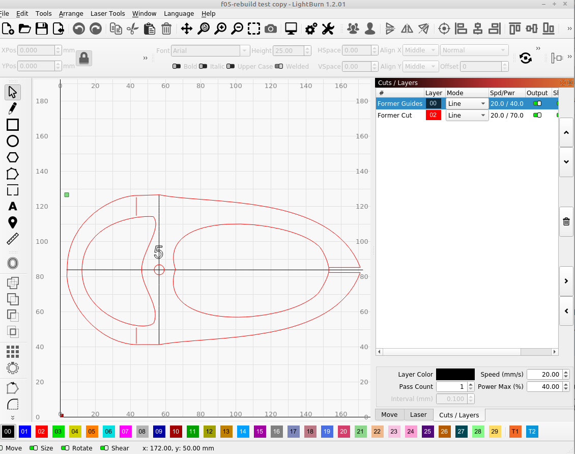
f05-rebuild test copy.lbrn2 (20.7 KB)
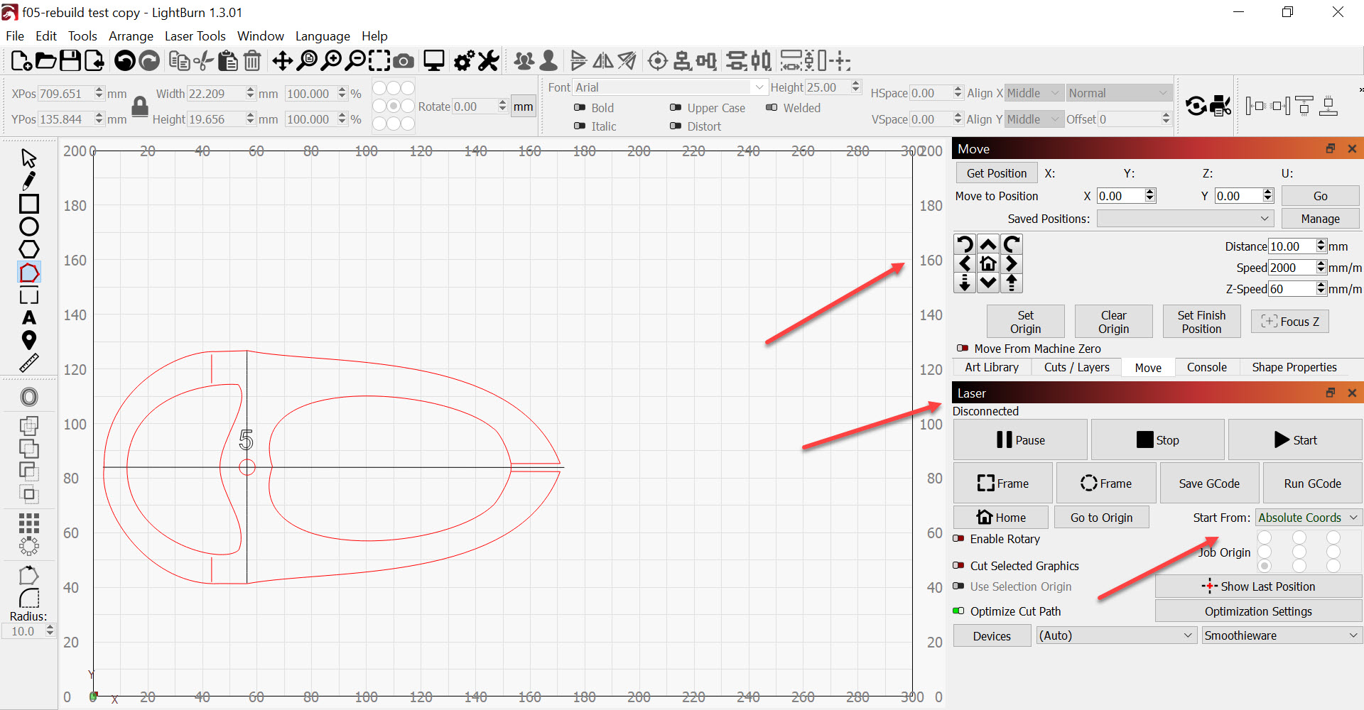
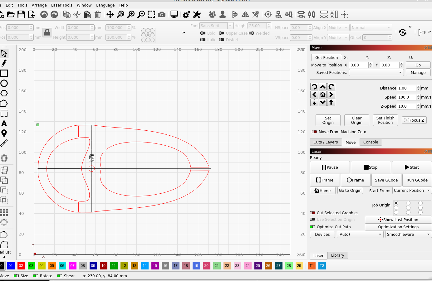
I need to see the other edge of the workspace, the laser window and the Start From and Job Origin settings.
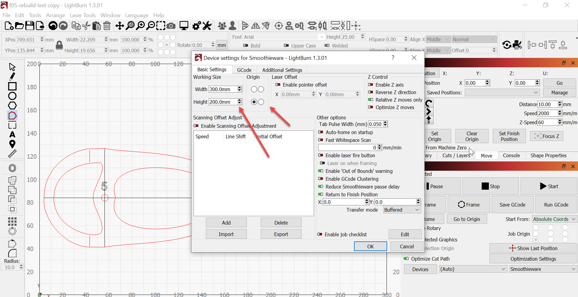
1…Larger screen shot
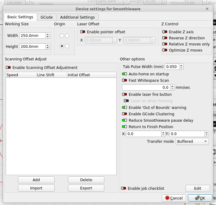
2…Device settings for Smoothieware
3…Edited config settings, turning off etc…
Does turning off mean cometting the lines out ?
Thanks Tim contact with John going ok
Trevor
1…Larger screen shot
2…Device settings for Smoothieware
3…Edited config settings as suggested and commented out the Alpha max travel and Beta Max travel lines, or should i set the 2 values to 0.
The comment in the code “NOTE set to nc if this is not installed” about setting uninstalled switch pins to nc is what I meant by turning off the switches.
I could have been clearer. This is not about turning off a switch that is not installed. This is about configuring Smoothieware so the pin we’re asking Smoothieware to check at the other end of the axis is not configured and the involved steps are skipped. The ‘option to omit’ has the unfortunate syntax: nc This conflicts with other grammar about switch states, NO for Normally Open and NC for Normally Closed. The correct way to reverse the pin state with the switch configured is to add ! to the pin number. The correct way to not look for or at a pin is to assign the switch behavior to pin number nc.
I now believe that I’m reading it correctly. These are the adjustments to the config file that I would test first:
alpha_max_endstop nc
alpha_max 250
beta_min_endstop nc
The rest is pretty close.
If I were feeling fairly confident about the Limit Switch Placement I would then test:
alpha_min_endstop 1.24 # Looking for switch near x=0 (same)
alpha_max_endstop nc # Not Looking for switch at the other end of X axis
alpha_homing_direction home_to_min # (same)
alpha_min 0 # Once we trip the switch, back off to release it (same)
alpha_max 280 # this is known and zero is set
beta_min_endstop nc # Not looking for switch near y=0 (new)
beta_max_endstop 1.27 # Looking for switch at the other end of Y axis. (same)
beta_homing_direction home_to_max # home toward the far end of Y axis (same)
beta_min 0 (same) This is known and the 220 will be set.
beta_max 220 # Once we trip switch, back off to release it and set 220 (new)
Either way, be sure to change the Device Settings in LightBurn so the Working area matches the firmware and be certain that these numbers are at least 5mm smaller than the absolute range of the machine.
alpha_homing_retract_mm 5 # distance in mm
beta_homing_retract_mm 5 # "
gamma_homing_retract_mm 1 # "
The engrave head runs over and trips the switch, then backs up 5mm and writes into memory.
No, and certainly not the homing maximums. I’m quite convinced those should remain considerably larger than the work area.
alpha_max_travel 500 # max travel in mm for alpha/X axis when homing
beta_max_travel 500
gamma_max_travel 500
The comment to the right of the number in the config file says the 500 is used for homing. I see in other controllers that it’s a standard practice to have the allowed homing distance to be quite a bit larger than the work area. When the engrave head gets to the switches the engraver knows where it is and tells LightBurn. It has to be sure to get there so these high maximums are commanded. If the engrave head doesn’t arrive at the switches when attempting to travel 500mm in each homing direction, it will throw the error in the Console window. We didn’t see this.
Hopefully,
- with the X axis and Y axis lengths corrected in the config file
- matching the Working Size (top left) Device Settings in LightBurn
- and both of these being at least 5mm smaller than the distance between the limit switches and hitting the frame on the other end of the axis
If this doesn’t sort it, we’ll go after the homing speed or ‘fast-seek’ next.