Hi
I’ve had my Ultimate Air Assist fitted and working well for a few months. It has just stopped working. I have traced the fault back to Pin 4 - Status on CN1. It is no longer grounding when the job runs.
Assuming it is a bad optocoupler and not knowing the spec for a replacement, can anyone confirm if its possible to transplant one from say Out1 or Out2 which are currently unused?
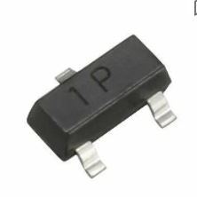
Glad you clarified. I see people blaming opto isolators all the time. It’s clear there’s something in between since it’s current rated to sink 500ma. P1 at Mouser comes back as a P-Chan mosfet, as would be expected
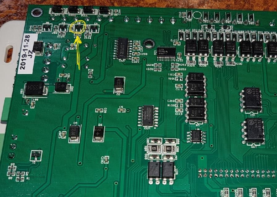
Too bad you didn’t post a photo of the locations of these.
I didn’t take a photo of mine but I did find this one and it being discussed on RDWorkslab forum in a thread on the subject that ended with no conclusion.
The controller is straight forward to open up. The 4-screws on the back to remove the cover and a further two passing through a small daughter board (USB’s and RJ45 interface board) which is plugged into the mainboard and into the case.
I saw that also, with the same conclusion. I was hoping for an epiphany from your labors
Thanks for posting it. I’m sure this is what’s failing, those mosfets. They are the protection for the optical isolators. Although they’ve only been around a couple of decades, I use them a lot on projects and find when they fail, they usually fail open. Which is usually a good thing.
I think there are only four sinks for outputs, so that would make sense. When I first saw that photo I was just looking into getting a CO2 laser and the controllers were still rather alien to me. Unfortunately there are still many alien controllers out there to me
As a curious question did you have protection diodes on that sink? I have run since I’ve got mine with a simple air assist valve for high pressure and have never placed diodes in the circuit. A few other users that have been up for years, claims none of his has them either. One of the Ruida manuals advises that it’s designed to drive solenoids, but another manual states there are no ‘back voltage’ diodes (I think is the term they used) in the circuit. I assume they mean these diodes. The question is in your experience, are they needed?
Unfortunately no epiphany and disappointed it didn’t turn to gold when I touched it.
I ran my Ultimate Air Assist which used ‘status’ as you know, yes, it came with diodes so I used them. I actually put another solenoid in there to open my compressor supply to air assist ( I think you mentioned doing your own in a thread commented in. The Air Assist had an extra Diode in the kit so used that for the extra solenoid. It’s been running well for quite a few months.
Personally I had never seen or heard of using diodes on relay coils before I installed the ultimate air assist. But then I’m not an instrumentation engineer. Maybe there’s a policy from Ruida et al of eliminating all possibilities to reduce the chance of warranty claims.
Edit: something I did notice that does actually make sense to me. On the optocouplers there are a couple thin lines marking one side of them a bit like a diode is marked. They were mounted on the board two to the right and two to the left. There’s the difference of the NO and NC I guess.
You only need to sense a change of state for the inputs. If you wish to run NO or NC just tell the controller.
It would make sense for there to be four of them. X, Y, Z, U…
I use status to operate the ventilation and the air pump via a SSR. That gives me low pressure air, the wind sink bypasses the air restrictor for full pressure, via the layer. Have my compressor out there and have connected it for experimental purposes. Will eventually have the full system and ditch the little aluminum compressor that came with mine.
Right now I’m in a kind of major upgrade or ‘remodeling’ job on my machine…
To start with, that “P1” is just an in-house identifier and unless you know the manufacturer, an approximate date when it was made, and probably the package style, “P1” on its own is more or less meaningless to the average consumer like you and I. The days of useful part numbers on the package are gone. The parts simply got too small.
You can find dozens of very different and very non interchangeable parts all labeled P1.
2nd, why would you expect a P-channel FET in a MCU controlled “low side switch” like this application?
An N-channel FET makes good sense. P-channel makes no sense and would be… difficult… to drive as a low side switch.
If I was looking for a replacement for those output MOSFETS I would be searching N-channel parts.
Something with the same package style (looks like maybe SOT23), the correct pinout, logic level gate, Vds > 40V, Id ~ 2A, Rds On = “lower is better”.
It’s a very non-demanding application and you can probably find dozens of parts that will work great at Digikey or Mouser for under $1ea in 10qty or greater.
LOL, no the MOSFETs are not protection for the optocouplers.
The MOSFETS are used on the output of the MCU as a low side switch in an open drain configuration. (Gate to the MCU, Source to ground, Drain is output). They are used to drive stuff connected to the OUTPUT of the controller.
The optocouplers are used on the INPUT of the controller to isolate and protect the inputs of the MCU. They have nothing at all to do with the MOSFETS on the output.
MOSFETS? They’ve been around since the 60’s and popular in tons of applications since the 80’s.
My first encounter with them was mid 70’s. But yeah, I’m an old guy too so sometimes it does seem like just a couple of decades…
Yep, excuse my blunder… I have used them since the 80’s… I have also used optical isolators to drive mosfets. The Ruida manuals are not clear on exactly how they use them They do show an optical isolator output
From the Ruida manual
“All outputs are isolated through the optocoupler, and 500mA current for each,
OC gate output, each can directly drive the 6V/24V relay.”
They would be smart to isolate the 5v logic circuitry from the 6v/24v ‘real world’.
Jeff, I’ve seen that in the manual also… But I’ve spoken to plenty of people that do not use them. Some have advised they are ‘imbeded’ in the solenoid. I don’t buy into that but some have run for years with no problems.
It was just a curiosity question. You’re right the diodes are cheap, I might just add them as insurance
Your probably right this thread should be put to sleep