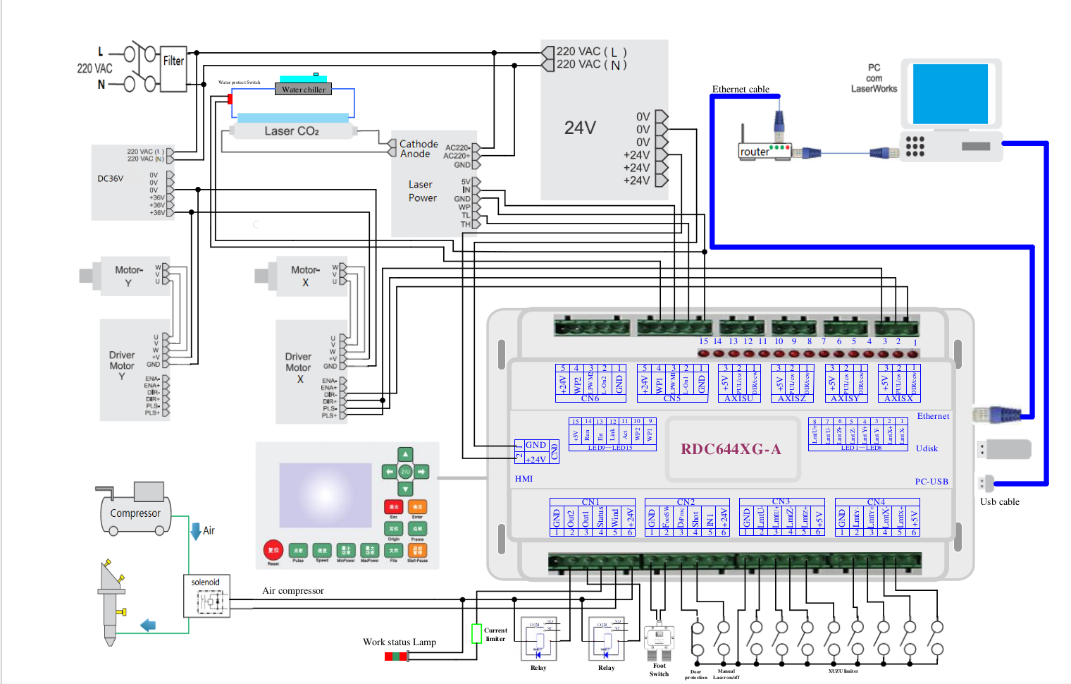
Hi. I tried to find the answer in the already created topics, but there is no scheme anywhere, and I don’t understand it very well myself. Tell me how to connect the stack lamp to the ruida controller, I know what outputs I need and what they are responsible for, but I need a circuit.
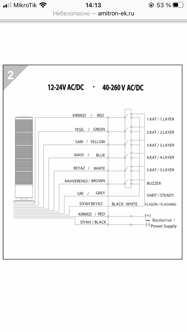
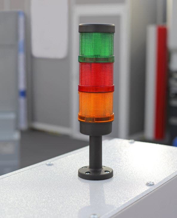
And will it be possible to connect such a column to the controller?
There are a limited number of connections to the controller. I know of no current controller that has that kind (number) of surplus outputs. What if you had 20 layers? As far as I know none of them will tell you which layer it’s currently processing.
It might help if we knew what you were trying to do… what actual use would you want it perform?
I want the controller to report its status (accident, operation, idle) and send a signal to the LED lamp.
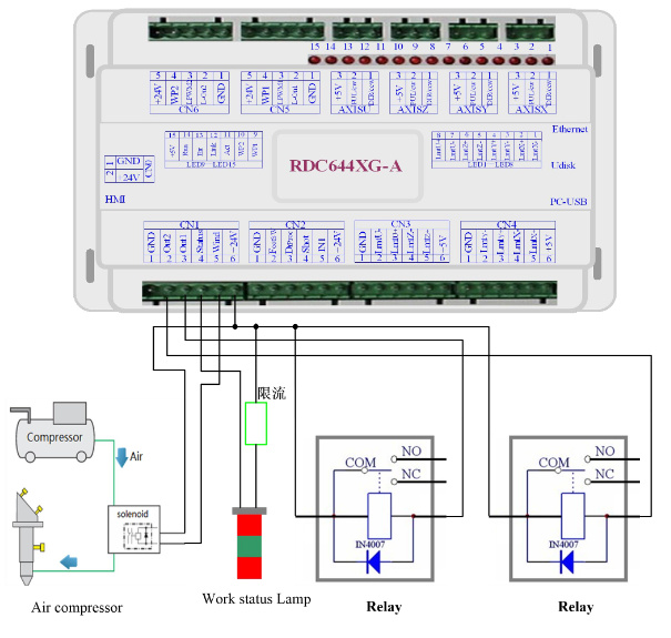
Judging by the previous topics, these inputs are responsible for this:
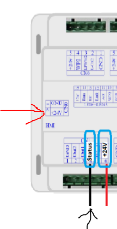
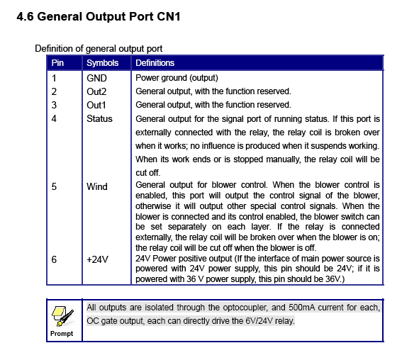
Output CN1 Pin 4 Status - the machine is running (yellow)
Output CN1 Pin 3 Out1 - the machine is idle (green)
Output CN1 Pin 2 Out2 - emergency stop (red)
Thanks for the link, however when a manual says “General output, with the function reserved.” it means you’re an idiot to use it since you don’t know what it really is. I’ve heard, mostly that the two Out ports follow the status port. It could be many things, but hanging an LED on something and making a determination on this is not the best practice.
Your question was to show the layers progress, this is not even related. Did I miss something?
Here’s the documented options from Ruida (English).
You cannot count on those outputs to be there. The next firmware may change that operation.
Have never checked mine, I’ll have to do that next time I’m out.
Oh yes, thank you, I also saw this video, in the comments the author promised to disassemble the connection of the control lamp with three indicators in the near future, but there are no new videos from him yet.
The manual says “General output, with the function reserved.” My years in hardware/software educated me that when it says that, you can’t depend on it. Even if you measure it while in operation, it could have some strange function you are not aware of or that on the next firmware upgrade it won’t work anymore.
I’d love to be able to use a couple of extra outputs, but I couldn’t in good faith encourage others to use something that I’m really guessing at.
Out1 sounds like it’s a NOT(status)…
If you’re not guessing, then can we all know? NDA between you and Ruida?
The graphic looks a lot like one from a Ruida manual… is that it’s origin… that would be nice… that graphics not in any of my three manuals…
Kind of a tip off
there’s some Chinese thought behind it…
If you want it to work for the product life, you can’t use anything that’s ‘reserved’ by the manufacturer. That term means they can use for and what they wish.
I suspect Lightburn has a better line into what these controller are capable of. The previous graphic probably came from China.
If it’s what Jeff stated, out1 is the inverted state of ‘status’ and some type of alarm for out2. What would you use these for? These machines are supposed to be ‘watched’ when they run because of potential dangers. If you are standing there and it has an error (or alarm) it will stop and display on the screen that it faulted. If it’s running, this is pretty intuitive.
Check out Davids link. I have a 6442G and don’t remember seeing that option.
I could see that in a room of them. Only in China…though.
I’ve been looking through these manuals. Most of the technical seems to contradict itself. One manual stated that it would drive 300ma, the other 500ma, same model. Some say reverse diodes are required, other do not.
Not sure if this helps, found reference to these on the RDWorks Lab forum.
I know you mentioned this but I was thinking that the note at the bottom was a bit of a give away giving max current the OC can handle and that each can drive a 6V/24? relay. So should be OK for an LED.
What does that mean exactly? We know the kind of opto isolators on that board or not capable of more than about 20ma… So what does it mean to the user that they are opto isolated?
One of mine says similar but the current limit is 300ma.
All of these people testing it with leds…
My point here is the documentation that we all reference says it’s a "General output, with the function reserved.”, that means they can change it at will and don’t use it.
I would have thought that the General outputs are provided so that Vendors can add options to the machines that can be controlled by the controller or through software. Opto Isolation may not mean much at all to the average user and most likely those same users wouldn’t be looking to modify their machines in this sort of way anyway.
For those that do have knowledge/ability then the freedom to make a few mods is there, as it is with vendors who build the machines using these controllers.
To me General Output means they are provided for exactly this reason. Function reserved may of course mean they can change it at will but as these are inputs/outputs, any change at will would be for controlling something additional wouldn’t it?
It could be the Chinese way of saying for example that these General Outputs are actually reserved for a Stack Light function for those that are used in industry and a stack light is a requirement.