Just installed LB trial for Mac to use with OpenBuilds Acro 1010 pen plotter and Blackbox. Goal is to use LB to translate Adobe Illustrator line drawings in to gcode to drive pen plotter as a special case of a laser tool. LB quits as soon as the connection wizard window attempts to search for machine type via USB. Acro 1010 is known to be working via USB connection and BlackBox Control software. Running MacOs 10.14. Ultimately I assume (tell me if I’m wrong) my workflow will be to open the LB gcode doc in BlackBox Control interface and drive the plotter from that control point - or is there a reason to drive it from LB once the USB connection problem is solved that is?
Turn off Bluetooth while scanning for the laser. Apparently the driver for Bluetooth headphones locks if you try to close it early. This is fixed for the next release already.
You get more machine control features if you drive it directly from LightBurn - the integration is pretty seamless.
I’m on a desktop iMac. If I turn off bluetooth I’ll lose my mouse. Is there another way around this problem?
As for choice of control, BlackBox has buttons/controls that allow for, among other things, jogging and setting a marked zero point. Another button maps a square boundary to show you max X and Y limits of the plot. Two other buttons raise and lower the servo. Very handy when loading and setting up the pen. These controls, plus a running log of the gcode are helpful. Are there equivalents in LB direct control?
It’s the bluetooth headphones that are the issue - if you disconnect those, and just have the mouse, it should be fine. You can also just cancel the ‘Auto’ finder and click ‘Create Manually’ and set it up by following the prompts, but the auto method takes a bunch of the guesswork out of it.
Everything you mentioned (except the servo, though you could do those with macros). And considerably more. You can select the ‘Locator’ tool and then just click in the workspace and the laser will jog there, for example, in addition to continuous and discrete jogging buttons, and the ability to enter a coordinate and have the laser go there. You can select an object and tell the laser to jog to the middle of it, or tell the system to move it to wherever the laser is. The list goes on. The full GCode log isn’t in the current release, but is already completed for the next one.
The mouse is my only active and connected bluetooth device. LB still quits as soon as the device wizard starts searching for a machine. I saw that manual mode but did not know what gcode choice to pick. Which brings me to the next issue.
I tried to run a simple test by using LB to create a square and circle graphic, which I want to save as gcode to run a test. Then if that works, go to the next step of importing an svg from Illustrator and do the same. But I have yet to figure out how to get LB to offer me the “save gcode” button in the gui so I can save and open it in BlackBox. I don’t know how to cut through all the laser cutting parameters in the gui to get to that point. Is there a settings file/list somewhere that can guide me to set up (minimize) the parameters such that I can define the simplest laser tool possible to function as a pen?
Not all lasers use GCode, so that option isn’t available until you’ve chosen one.
The OpenBuilds Black Box is a GRBL device. Choose GRBL from the device list, and you’ll need to choose the connection (USB), origin point, enter the working area size, and whether to home it on startup. You can change these easily later if you get any wrong.
This is “better software for laser cutters”, not pens. 
That’s a cheeky answer, but it’s also true - pen isn’t a standard tool for lasers, nor is it standardized with GRBL. Different kinds of pen attachments behave differently, so how it’s controlled will depend on that.
If it’s a servo type, using the PWM / spindle output to control the height, it’s easy - you just set a Max Power value for the layer that’s appropriate for lowering the pen to the correct height and you’re basically done.
If it uses the Z axis to raise/lower the pen, you’d create a layer with a Z-offset into the work area, and you’d have to enable Z moves in the device settings (most laser users ignore the Z for everything but setting the focus).
Dug up a very old corded Mac mouse from my computer boneyard to enable me to turnoff bluetooth completely. That worked, sort of, allowing me to boot LB without it quitting when searching to set up a device. But it could not fine the Openbuild Blackbox so had to do it manually. Of the three Grbl choices offered, the plain “Grbl” one worked. There is a choice labeled “Grbl 1.1e or lower” but could not get that to work. The latest Blackbox firmware says version “Grbl 1.1f” if that is the issue. Set up a simple first test of a simple rectangle and polygon in LB. LB ran thru the plot in realtime (that’s an advantage over Openbuild) and from gcode file too however, the servo action on the pen holder was all screwed up - either going in the wrong direction, or not moving at all between objects. After going thru a one time servo setup procedure in Blackbox to find the proper values, Blackbox plants “M3 S201” for servo up and “M3 S153” for servo down in its gcode script at all the right places. Is there a way to get LB to do the same? Also, when does LB expect to release the fix for this Mac USB problem? Thx
Hoping for a release within the next couple weeks.
There isn’t a way to get LightBurn to do this at the moment. Those are backwards to normal laser moves, where S0 = off and Sxxx is on.
Then how can I solve the problem of servo control in order to use LB as a pen plotter driver and/or gcode generator? That means I cannot use it for realtime gcode plotting. Does that mean in theory I would have to edit the gcode in a text editor and manually insert the servo command values? If so, that’s not a trivial thing to do considering I will have 100s, if not more, vector paths imported from Adobe Illustrator. Each will require a “servo up” and “servo down” command bracketing each isolated path. Is there no way to route the intensity PWM command parameter to the laser to a servo value as a workaround? If not, what other actionable parameter generated by LB might I be able to use? Blackbox services lasers apps and besides providing a PWM output, has a “tool” output as well. It’s a user defined on/off logic level. it’s a bit Rub Goldberg but I think I could translate a logic on/off signal in to two PWM servo values using a 555 timer chip. That said, this process makes me feel like I’m the first person to ever want to make a cnc servo controlled pen plotter. Surely others have solved this fundamental issue - no?
Follow up question. If I can’t get LB to issue “M3 S201” and “M3 S153” to bracket the paths, is there a way to get it to insert two distinct gcode commands - of any kind pertinent to laser - around each segment in the gcode, which I could then hunt down with “find and replace” in a text editor?
Indeed they have, as noted in the thread you started previously:
If you use the ‘GRBL-M3’ profile instead of ‘GRBL’, LightBurn emits an M3 / M5 pair around every vector cut. Rasters will not behave because they use constant speed and just toggle S0 / S### for the scan lines.
OK I’ll give that a try.
The lack of a built in LB gcode editor means I lose the ability to run the plot in realtime, but I’ll accept the compromise for now as long as the workflow is manageable. Thx
Could not get it to work. Here is code “before” modifying
; LightBurn 0.9.09
; GRBL-M3 (1.1e or earlier) device profile, absolute coords
G00 G17 G40 G21 G54
G90
; Cut @ 100 mm/sec, 20% power
M8
M5
G0X21Y25
M3
G1Y92S51F6000
G1X105
G1Y25
G1X21
M5
G0X121Y66
M3
G1X142.25Y91.98
G1X184.75
G1X206Y66
G1X184.75Y40.02
G1X142.25
G1X121Y66
M5
G0X144Y100
G0X133Y109
G0X121Y123.81
M3
G1X99
G1X88Y142
G1X99Y160.19
G1X121
G1X132Y142
G1X121Y123.81
M5
M9
G1S0
G90
; return to user-defined finish pos
G0 X0 Y0
M2
here is the code after modifying
; LightBurn 0.9.09
; GRBL-M3 (1.1e or earlier) device profile, absolute coords
G00 G17 G40 G21 G54
G90
; Cut @ 100 mm/sec, 20% power
M8
M3 S201
G0X21Y25
M3 S153
G1Y92S51F6000
G1X105
G1Y25
G1X21
M3 S201
G0X121Y66
M3 S153
G1X142.25Y91.98
G1X184.75
G1X206Y66
G1X184.75Y40.02
G1X142.25
G1X121Y66
M3 S201
G0X144Y100
G0X133Y109
G0X121Y123.81
M3 S201
G1X99
M3 S153
G1X88Y142
G1X99Y160.19
G1X121
G1X132Y142
G1X121Y123.81
M3 S201
M9
G1S0
G90
; return to user-defined finish pos
G0 X0 Y0
M2
Servo did not move at all. Zero. Did I not do it right?
LightBurn also sets the S parameter with each shape after the M3 command. You’ll see it like this:
G1Y92S51F6000
If you change your layer power to 60%, that will just output S153 again (60% of 255).
Aside from that, I can’t see why that wouldn’t work, but I don’t know the specifics of what the pen tool needs to make it work. You could still be missing something.
Here’s an example gcode from OpenBuilds. This comes from three shapes made in Inkscape, then converted to gcode by Openbuilds. A dialog box is offered in the app with a place to enter numbers from 0-255 for the up and down range of the servo throw, prior to generating the code. This file moves the servo properly. I can’t see why the Blackbox hardware would know or care what made the code - unless see a difference that would trip it up coming from LB.openbuilds code example.txt (18.4 KB)
They’re also inserting a 0.5 sec pause after each servo command - it’s possible that’s necessary.
M3S153
G4 P0.5; Tool On
; stuff here
M3S201
G4 P0.5; Tool OffOk. Spent the day yesterday trying to wrap my head around this servo control issue between LB and OpenBuilds BlackBox (BB). LB broke 2 servos (good ones - metal geared) before I finally figured out the cause. Understand I’m speaking from only a cursory knowledge of the workings of Grbl and gcode.
I have no problem with the sync and the range of servo movement when using OpenBuilds CAM to generate the gcode. That’s bc BB issues a string of Grbl commands immediately upon serial connection to the BB. Openbuilds Control settings.txt (2.8 KB) Among these settings is $30=255, $31=0. The max/min spindle range. Apparently OpenBuild (OB) uses these parameter boundaries, in combination with a servo wizard tool, to help the user find the optimum hi and low servo values numbers to use. For the case of my custom pen holder the values are S201=up and S153=down. For the case of LB however, I don’t have the benefit of these settings so irrespective of misplacing the M3s as i did, the servo moves to the extremes at times during the plot, and out of sync, and thus breaking it. (2 of them).
So my questions are - do I have this right? If so, what among the Grbl settings you see do i need to implement and how do I do it? Your LB Grbl 1.1e device dialog offers “Edit” but that feature is mostly limited to a fixed set of values to pick from. Important to note, like BB the servo must be protected against traveling beyond the designated up/down values at all times. Not just when a gcode script is loaded. The servo can easily break if mishandled.
As for the workaround for inserting M3s in the LB generated gcode script, I obviously did not get it right by simply replacing the M3 and M5 “placeholders” generated in the LB script with M3 S201 and M3 S153 servo values when you exam the before and after changes I made in the txt files included here.LB first test before.txt (438 Bytes) LB first test after.txt (481 Bytes). Where did I go wrong? In the real application there will be hundreds if not a thousand or more open ended vectors, each requiring the proper servo command before and after. This can only be done via find-and-replace in a proper text editor with “zero” margin for error. As such, can you pls edit the “before” version to show me how it should be done?
As for the added “pause” value you noted, thx for pointed that out. That is a must now that I think about it. It takes a finite amount of time for the pen holder to change its mechanical position so that must be included in the “find-and-replace” method I envision - unless of course you can suggest a better way to implement it. BTW - that pause statement is inserted by OB’s CAM software, not at the BB control level. There is a “dwell” parameter I was not aware of in CAM that inserts this value in the gcode whenever the user selects “pen plotter” as the gcode tool in CAM.
Finally, it has been suggested the laser “power” be adjusted to “60%” in the gcode, which equates to S201. I do not own or operate a laser so sorry I have no idea what you are talking about, in words or the line of gcode you offered. Can you be move specific and/or offer an example with explanation?
Finally, on a similar note, I have read in the forum something about using LB’s laser Z axis layer to signal a servo value change for those with a desire to use LB for pen plotting. Would that be a better way to go than to repurpose the Grbl spindle parameter method - in the context of LB software?
Thx
Let’s be clear here - You broke those servos while trying to get LightBurn to do something it’s not designed to do. Lay the blame where it’s appropriate. If I spill my coffee while trying to stir it with a canoe paddle, it’s not the fault of the paddle. ![]()
Here’s my take on the changes needed. Understand that I don’t have this device, and I’m going on what you’re telling me.
LB first test-Edited.txt (524 Bytes)
I said “layer power”, not “laser power”, meaning the power setting of the layer you’re using in LightBurn, set here:
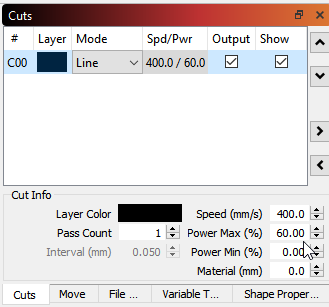
The ‘60%’ in that box tells LightBurn to emit an S parameter (which is normally used to control the laser power or spindle RPM) of 60% of the total maximum output. You’ve told the system that the maximum is 255, and 60% of that is 153. It will produce an S command of S153 by setting that power to 60%. It will also produce S0 commands to turn “the laser” back off again, because it has no idea you’re using a pen, and you’ll have to remove those (as I’ve done in the above).
Tried what you recommended. Set the layer max pwr to 60% with Output and Show boxes checked. This is the gcode I got as a result. LB servo test_2.txt (439 Bytes) As your can see there is no S153 or S0 statements. Just M3s and M5s. Did I miss a step? Also, the min pwr value field was greyed out. Is that a clue? The good news is, it looks like the M5s and M3s in the right places in the code to search-and-replace in a text editor. BTW - is it OK to put the S value and delay code on the same gcode line?
You say 60% pwr equates to S153 on the scale of 0-255, but what tells LB what the scale is? For the case of OB/BB they load $30 and $31 values that define the range for the spindle/servo S values at the time of USB connect. You see this in the Grbl settings txt I sent last time. Whether it’s 30 and 31 or something equivalent for the laser world, the critical thing is to never allow the servo to be exposed to values beyond the predetermined up and down values of the pen holder - either at the time of pwr up or any other time during operation.
(BTW - I pulled the replacement servo out of my pen holder and let it float in space for testing purposes to reduce the risk of another one burning up)
Something else changed in this test too. Yesterday, before the servo(s) broke, I was able to type manual S vales in the LB console to make the servo move. Today that no longer works. Yet over in BB I can make the servo move via its console no problem. What could cause that to change?