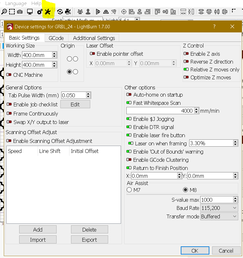
Did you setup your Laser as GRBL?
Is your laser $30 = (Ligtburn S-Value max) = 1000 ?
No , and I have never done a setup as you ask. Just how do I do that? I clicked devices and LB found my laser and gave it comport 7. However, when I click devices the window never says or shows that it found the laser, but when I scroll down to very bottom of the list that shows GRBL, it shows my laser and comport number. If that means anything.
Randy
Paste here an image of your device settings.
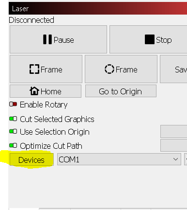
Click Devices button an past here resulting image
.
Type $$ in Lightburn console and copy/paste here the output.
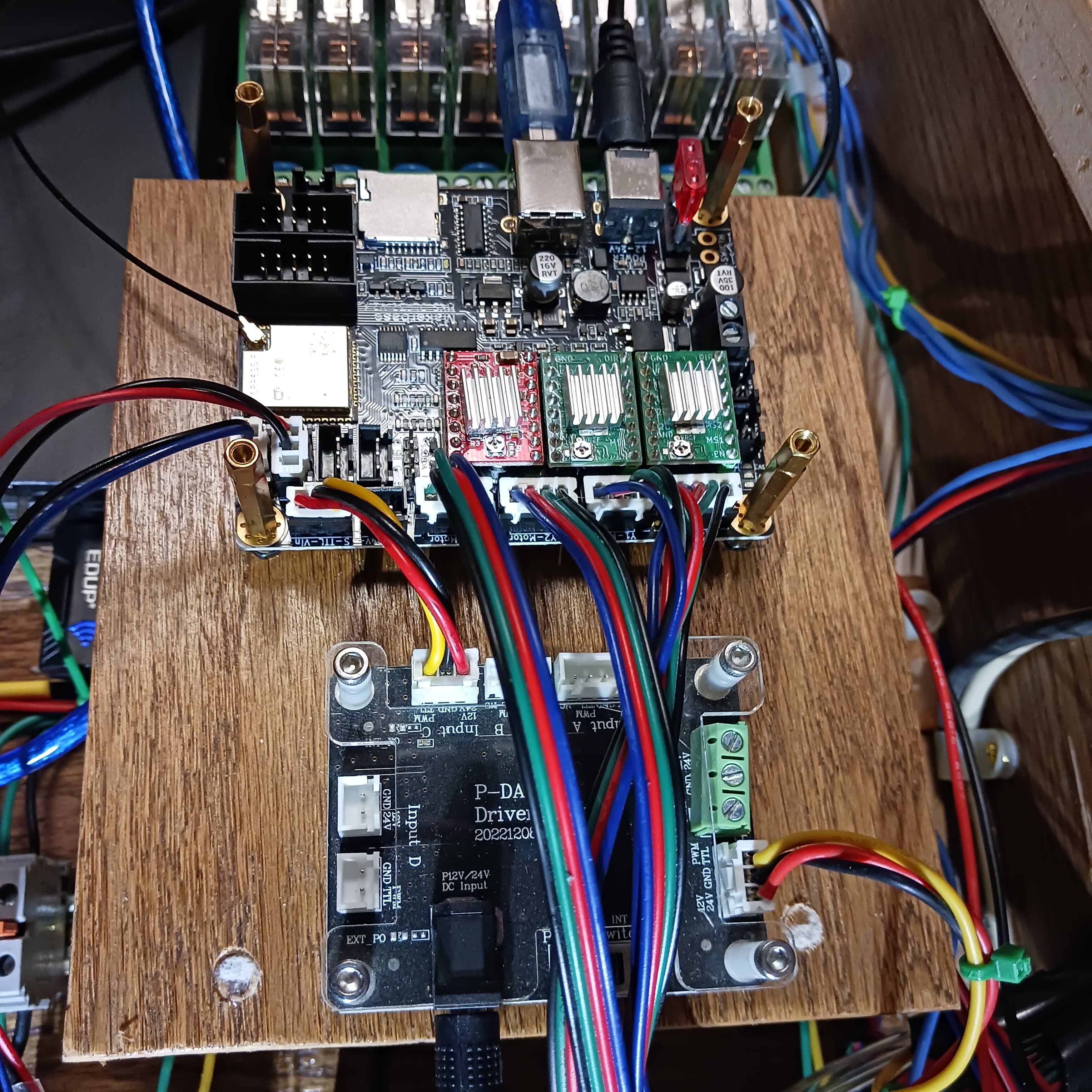
Your Lasertree LT-4LDS-V2 came with an adapter board, are all plugs well plugged and the switch in the right position?
The LEDs of the adapter board are lit (power Led ON, PWM ON when running a job)?
Hello Parsec - Yes I did, even had to manually create my g-code. Everything works as it should, only still has same problem with the laser itself. I even hooked up the controller to a second PC with LB and again everything works as it should, but it still has the same laser problem. I have tried the laser with and without the driver board, same problem. My MKS is powered by a 24 volt - 20 amp power supply so I don’t need the driver board. At this point I think the problem is the laser itself. I finally found an email to support at Lasertree and sent them a note requesting electrical schematics to the laser. Now the waiting game.
Will get back later and thank you. Randy
A new update: The problem is the laser itself. I unplugged the 24v. power and unhooked the lasertree laser, then I hooked up an old 12v ortur laser and its power supply. Ran a test and EVERYTHING works perfect!! So far I have contacted Lasertree three times now and still not a word back from Lasertree support team. I now feel that lasertree is a fly by night trashy company. Screwed me out of 300 bucks!
OH well, lesson learned the hard way. Time to start looking for a new laser. If anyone has any suggestions for a good laser module, please let me know.
Randy
1 Like
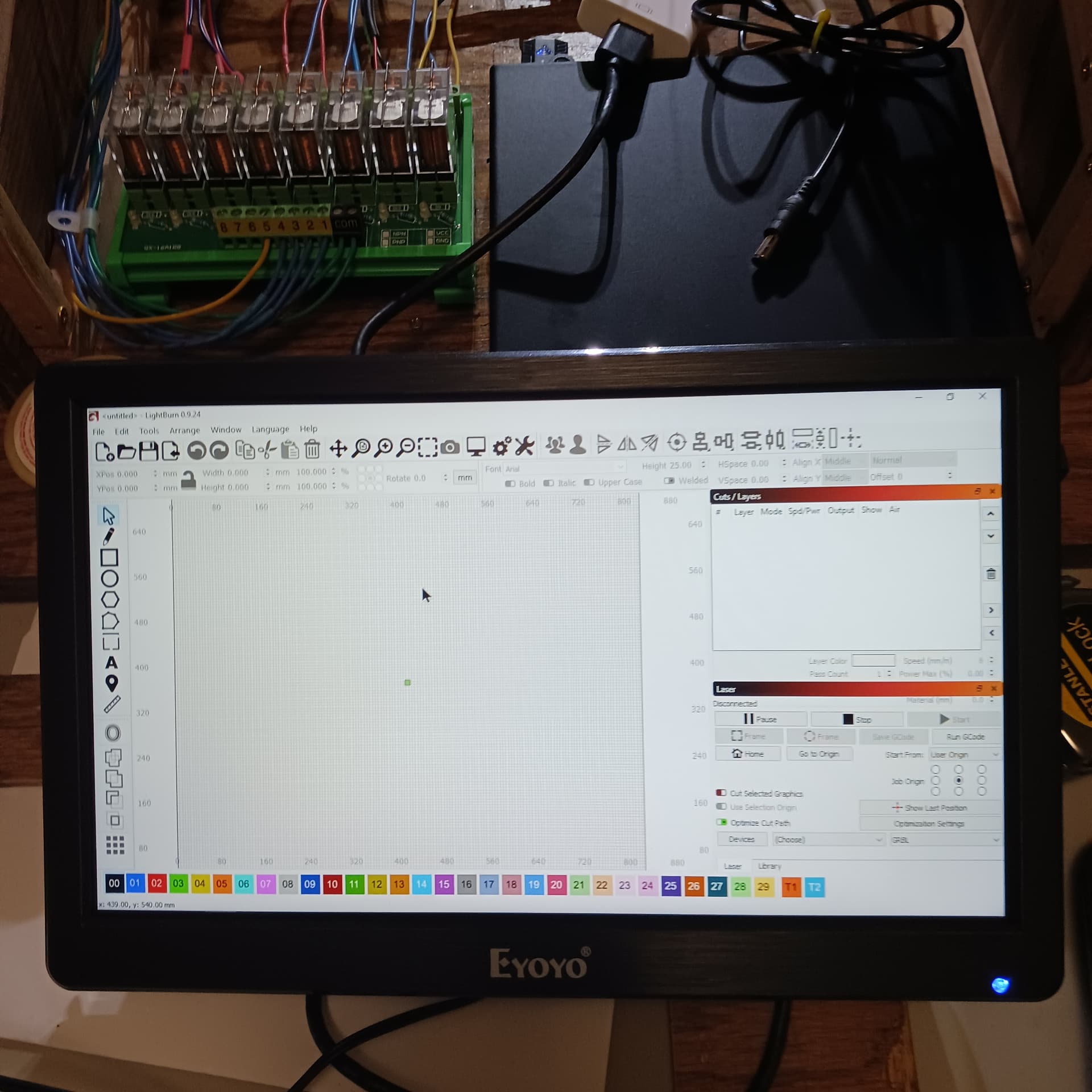
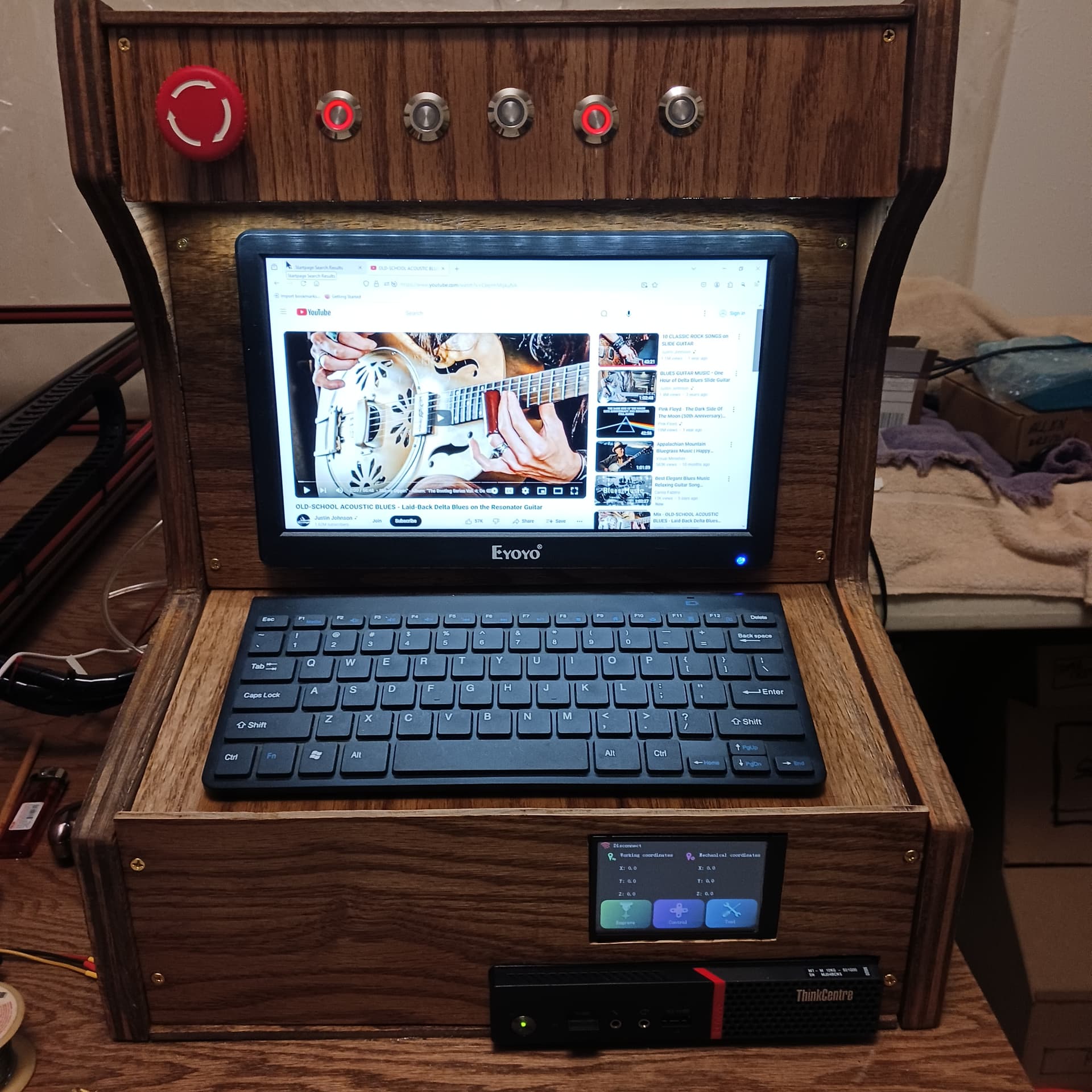
Hello All: I got my screen size problem solved. I went from an 11" to a 12" screen.
Everything can now be seen. I’m happy. I found a 12" screen for $45 plus tax and free shipping. ------ After 4 emails and 16 days later I finally got an answer from Laser Tree. In fact I got 5 or 6 emails and they are bending over backwards to help me. I told them in one email that I wanted to fix this one and not get a replacement. So they sent several pics of the guts and they even sent me the schematics to my K-20 as well as some disassembly info of laser, press here, press there, pull here and get a bigger hammer!! Anyway, here is a shot of the new screen and everything can be seen now.
More UDs coming soon.
Randy
1 Like
WOO HOO !!! I got everything working right , FINELY !!! What was the problem?
It turns out to be the USB to Controller board cable was faulty. That was the only thing I failed to check and that was it. I have a bad habit of buying one to use and one to loose.
When I thought about the cable being bad, I got the cable out the spare controller kit and that one worked. I feel really stupid sitting here thinking how I spent 4 to 6 weeks crying and trying to fix this thing and never thought of checking the usb/controller cable “UNTIL” tonight. Yep! Tonight as in a couple of hours ago!!! Now its time to mount the new screen and button things up for now. I’ll post a pic or two after I button it up.
That’s all I have to say for now other than HOT DANG IT’S A WORKING !!!
Randy
1 Like
Ok – here is the console buttoned up from the front.
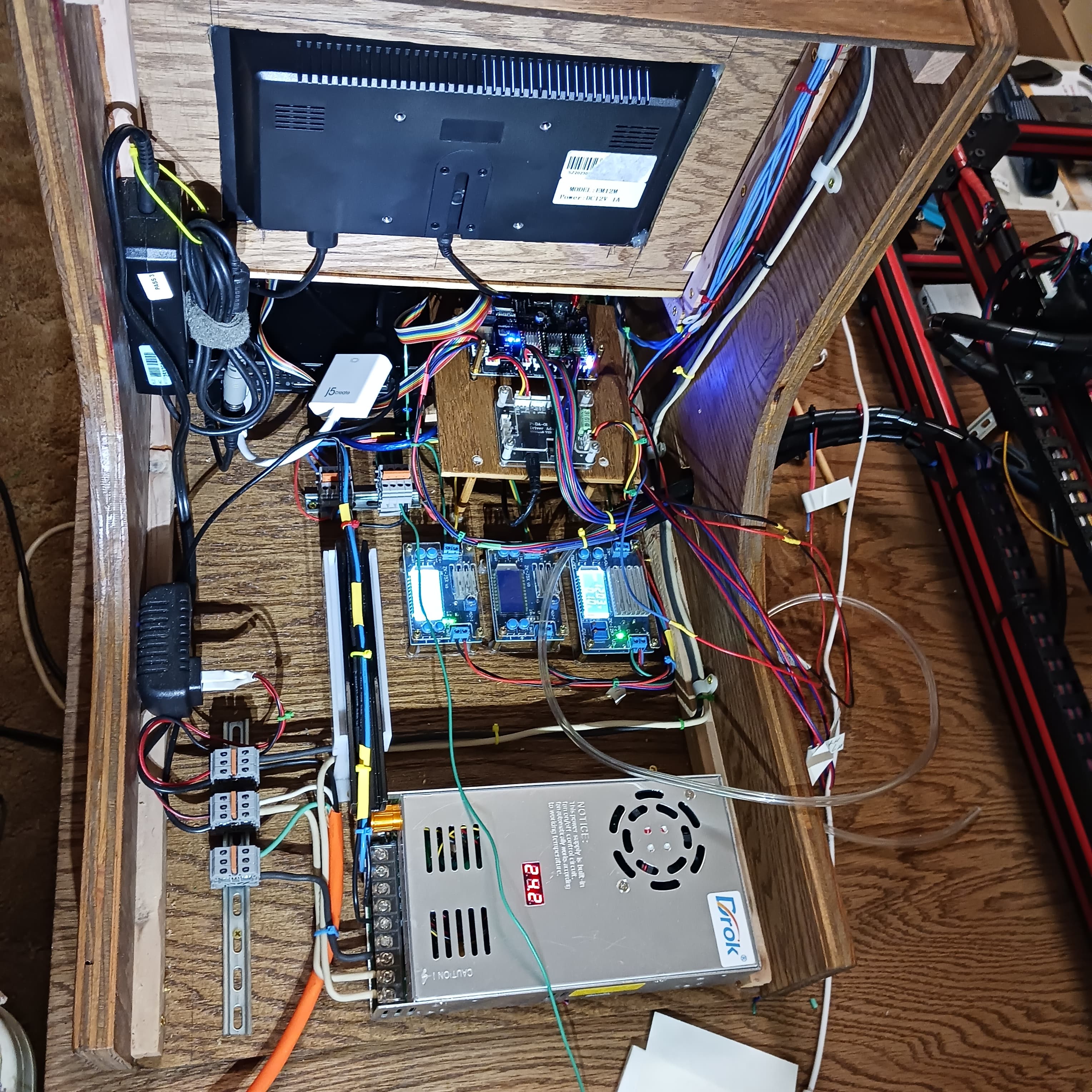
Next is back side, there are 3 pair of wires hanging right now that come from 3 spare relays plus another pair for 2 console cooling fans. Also you will see the air line coming from the laser.
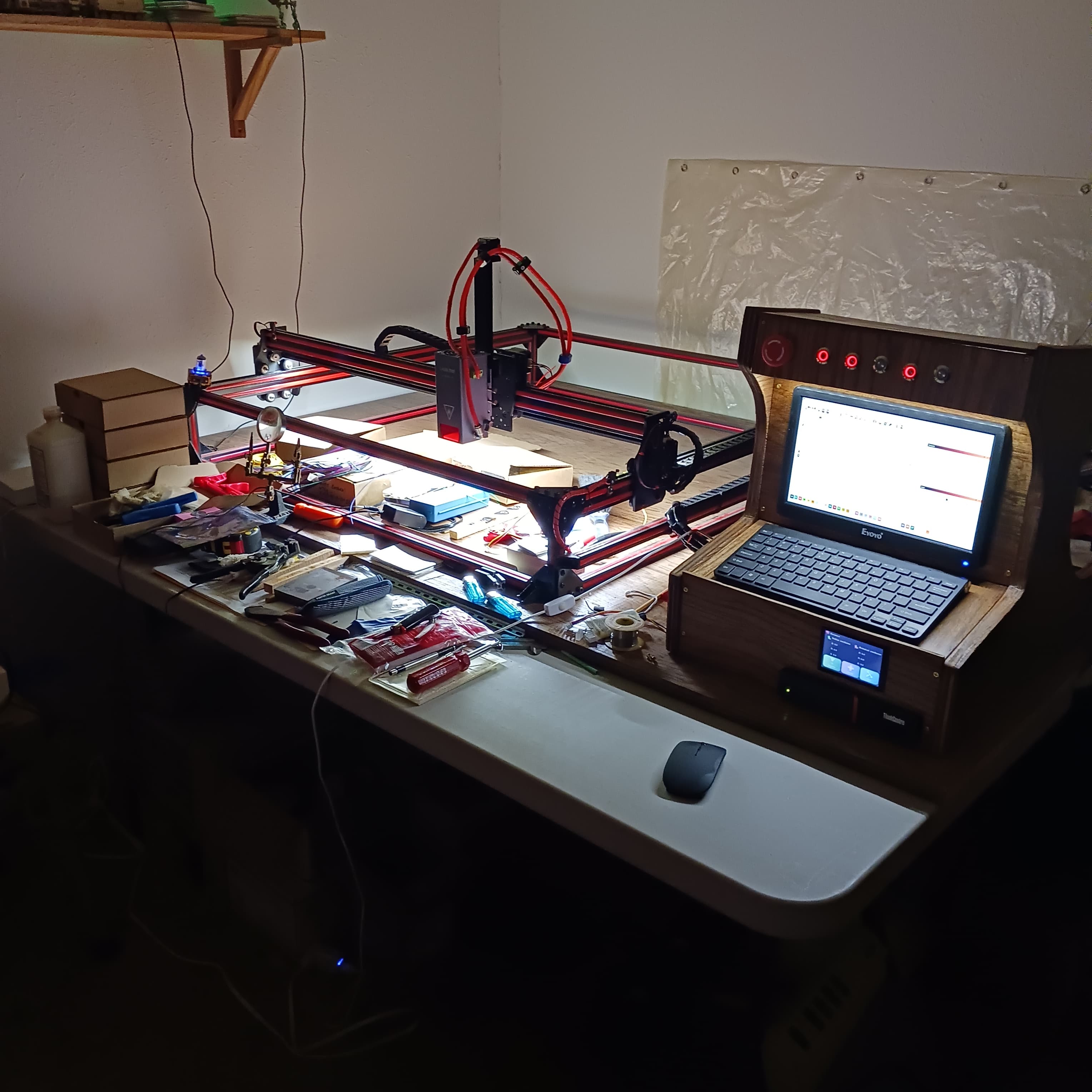
and last is a pic of the whole thing mounted to 4’x6’ sheet of 3/4" stained red oak. Just over look the tools and parts still laying out!
More info coming later, I’m starting to order parts for the gas evacuation box which will be a big box. (46" W. x 45" D. x 21" tall) If I’m lucky I might be ready to make my first cut/etch project in time for Xmas.
OH OH OH – a few days ago I got my number 6
grandchild, lives in FL. A little girl at 4 lbs. I not sure just what her name is or how to pronounce
her name so I’m going with this for a name, Lyndela, I think. Lyn-del-a. Kids now days and their stupid names. Anyway she is cute but will be in hosp. for another month or less due to lack of weight.
Oh well, time for me to go now. – Bye Bye
Randy
1 Like
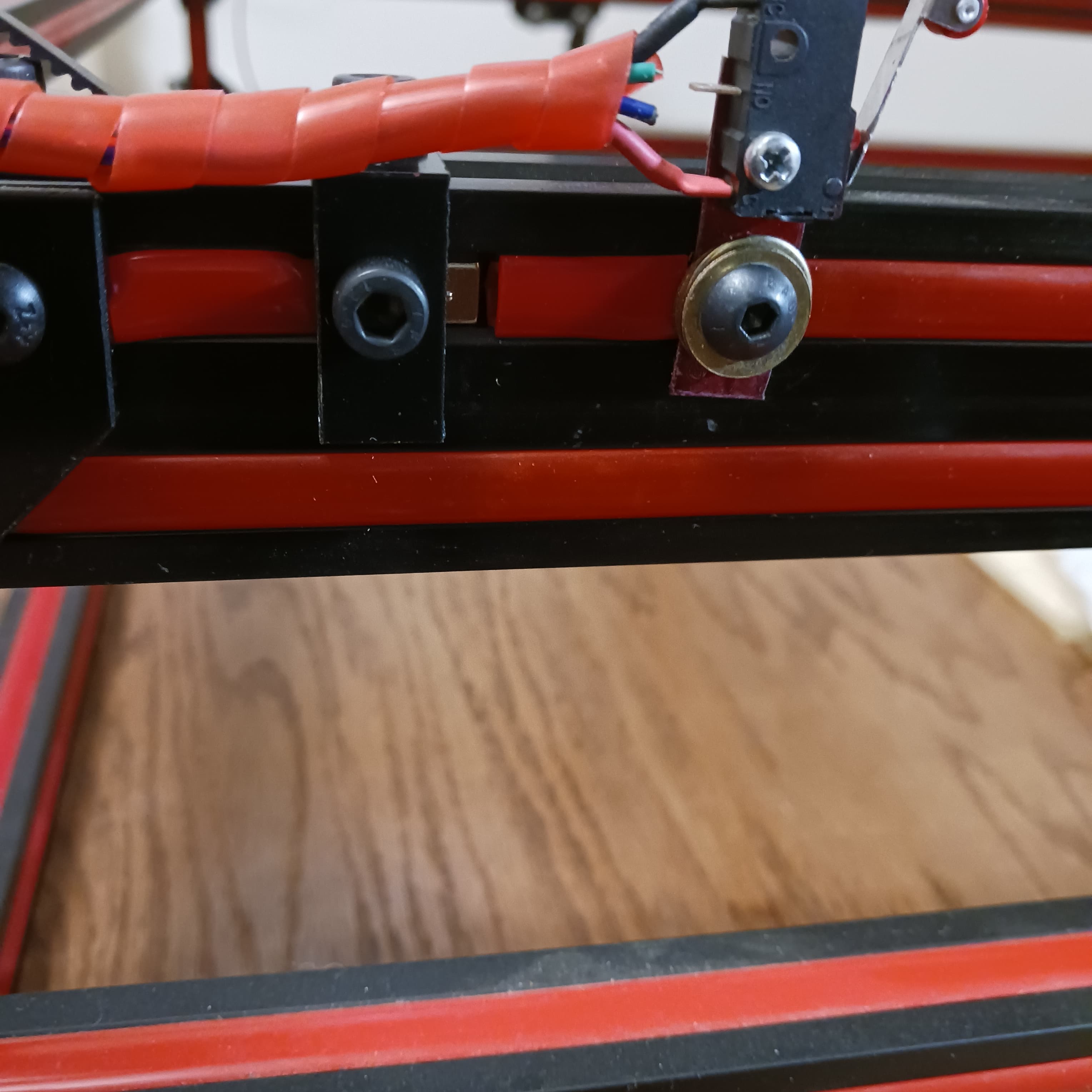
I got my “X” drive cable install, works good. Now for clamping down the two “Y” drive cables. I cut four pieces of 1" x 1" x 2mm aluminum angle iron and drilled one hole so an M5 screw would slide through on one side and drilled a smaller hole on the other side and tapped out that hole to M5 screws. Looks good, I thought it wold work great. Then I ran into a problem, I discovered that there were only and barely 3 threads in the alum., (2mm thick) for the screws to grab onto. When you tightened the screws tight enough to hold the drive cable, (timing belt) secure it would strip out the threads in the alum. Time for another drive to big city for another piece of alum. at 1/8" thick. That should work!
Anyway, here is a couple of photos to show what I’m after.

And I was going to make test runs tonight also.
Not now, maybe tomorrow night!!
Bye Bye for now.
Randy
2 Likes
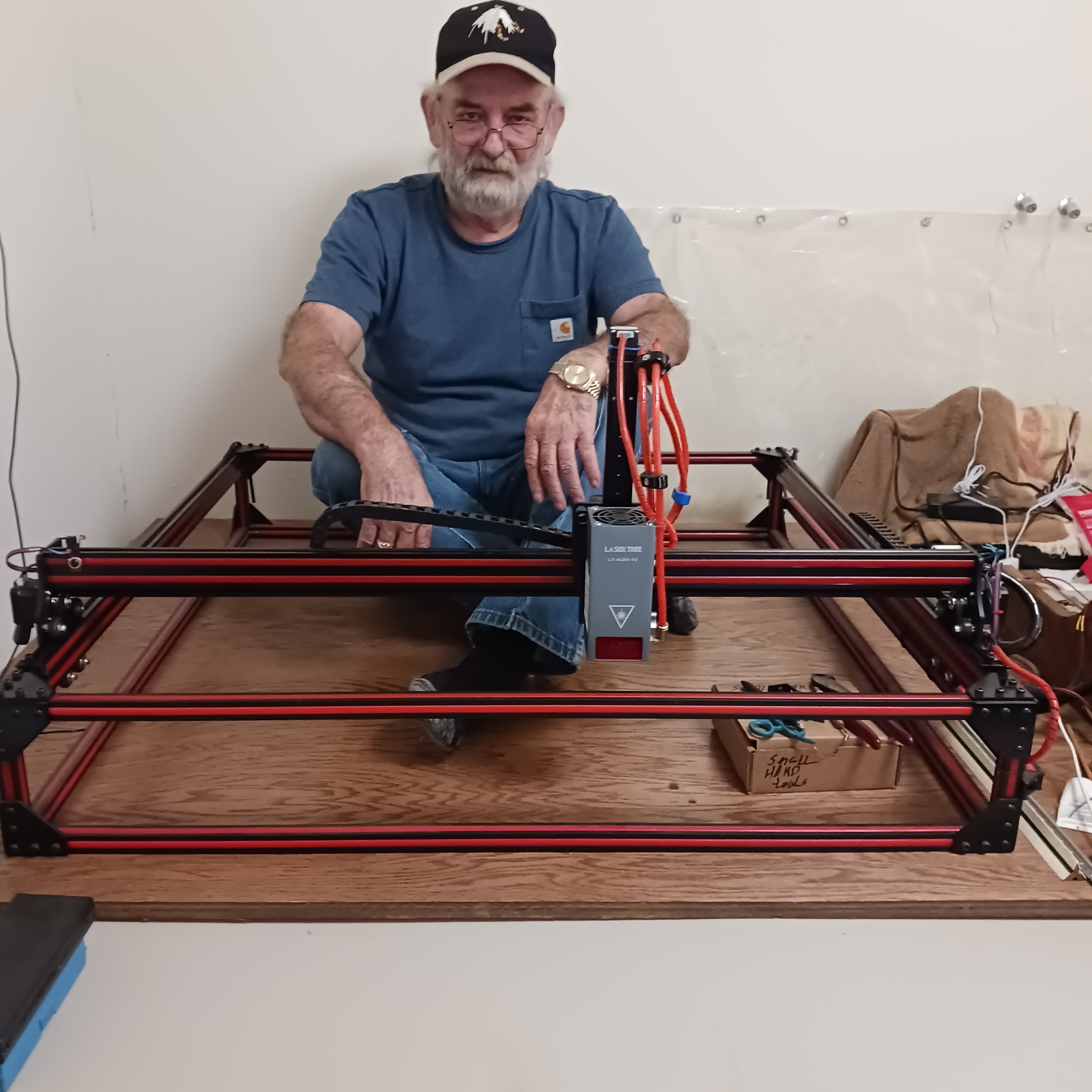
OK – got the new 1/8" thick angle aluminum timing belt clamps made, drilled, threaded and painted. They work great !! In order to reach the back of “Y” axis I had to climb up “into” the rig to get the clamps mounted. While I was up there my wife wanted a picture of me. So here is a pic showing how big the rig is. So don’t laugh at my ugly old face and yes I am smiling. Somewhere in L.B. I read a post that said I could add “.txt” at the end of the file name it should play in L.B. If it works I’ll post a test running video of the rig.
Randy
5 Likes
The forum as limit per file of 4MB.
hello parsec – are you talking about video file? I think you are.
Randy
1 Like
I need help PLEASE !!! My problem is this, I make box/square in light burn and I place this box/square in the center of my grid and I click frame. Works great, now move that box/square to another location on the grid and the laser should move to the new location and do its frame thing. Well it doesn’t do that, it just keeps framing in the center of the grid. If I change the size of the box/square, the laser does not frame the new size, it only frames in the middle of the grid and still only frames the original box/square. If I trash that box/square and draw a new one in a different location on the grid, the laser goes to that new location, does its frame thing just fine. After that it only does the same thing as I mentioned above. One more thing is that no matter how small or big the the image is, Light Burn keeps saying the image is out of bounds. One more thing, when I move “Y” axis to the front of the laser bed and tell the laser to move to the back end, the laser only moves about 75% of the way back and then acts as if it hits an invisible limit switch and stops and you cannot force it go any farther back. Does anyone have any ideas on to correct this problem? I also found nothing so far in You Tube pertaining to this problem.
Thank you for your time and concern in this matter.
Randy
What is your ‘Start From’ set to?
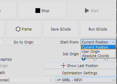
If ‘Current Position’ or ‘User Origin’ that could explain framing in the same central location.
Colin:
I have been using “User Origin” for 3 years now on 4 different lasers. Set Origin is like telling the laser this is your starting point while Set Finish Position is like telling the laser this is home now and this is where you go when job completed! I keep both settings in the center of my grid so my laser always starts for center of grid and returns there. If I set a project off from the center grid and I hit frame or start, the laser runs over to project does its thing and then runs home (new home).
I have been running the same L.B. (9.24) every sense May of 21,( I think it was May). I have been running all my lasers from a floor desk PC, (to big and heavy to be a desk top) that a late friend of mine built for me back 2005!! Never have had a problem yet with it.
Now the PC, (the Beast) is still running Windows 7 Pro, works like a charm for me while the mini computer, (Lenovo Think Center) that I bought for the Cherokee Beast laser is running Windows 10 and I have L.B. 9.24 installed on it also.
Now for strange parts, both L.B. programs work different from one another. What I mean is, on my floor deck pc, you open L.B. and you have an empty or blank grid. You want to draw a square so you click the square button, draw your square and now you go up and click the pointer button to turn off square drawing. When I turn off the square button my square “highlights” as I call it.
That is when your square becomes a dotted lines with 9 little squares and the corner rotation arrows and you can resize, move or rotate your square, that’s cool !! On the Windows 10 pc, when you turn off the square maker button, you square doesn’t highlight. The only way you can get the square to highlight is put your pointer on the square, then right click and then choose select all. And that makes every image on your grid highlight and that’s not cool !!
In Win 10 the laser “won’t” fire using frame or not and the enable fire button is turned on. If I click “start” the laser operates as should.
In Win 7 the laser “will” fire using the fire button. But when you click frame, no laser fire. Click start and it operates as should.
Win 10, all move controls are reversed and Win 7 all operate as should.
I have double checked, ( at least 50 times), that all settings in both Win 10 and 7 L.B. are the same and they are.
And I still have not figured out how to change the boundaries yet.
Is there place in lightburn that has upgrade where I can just put in my new lic. number or do I have to download the trial and then put in the lic. number?
thanks — Randy
Well, I got everything figured out and working except for the work area and I’ll be changing that later tonight. I found a lot of good help in another forum. I was impressed on fast I got help right off the bat.
More coming later.
Randy
A little U.D. here.—
I went to another forum that I am a member of and asked for help.
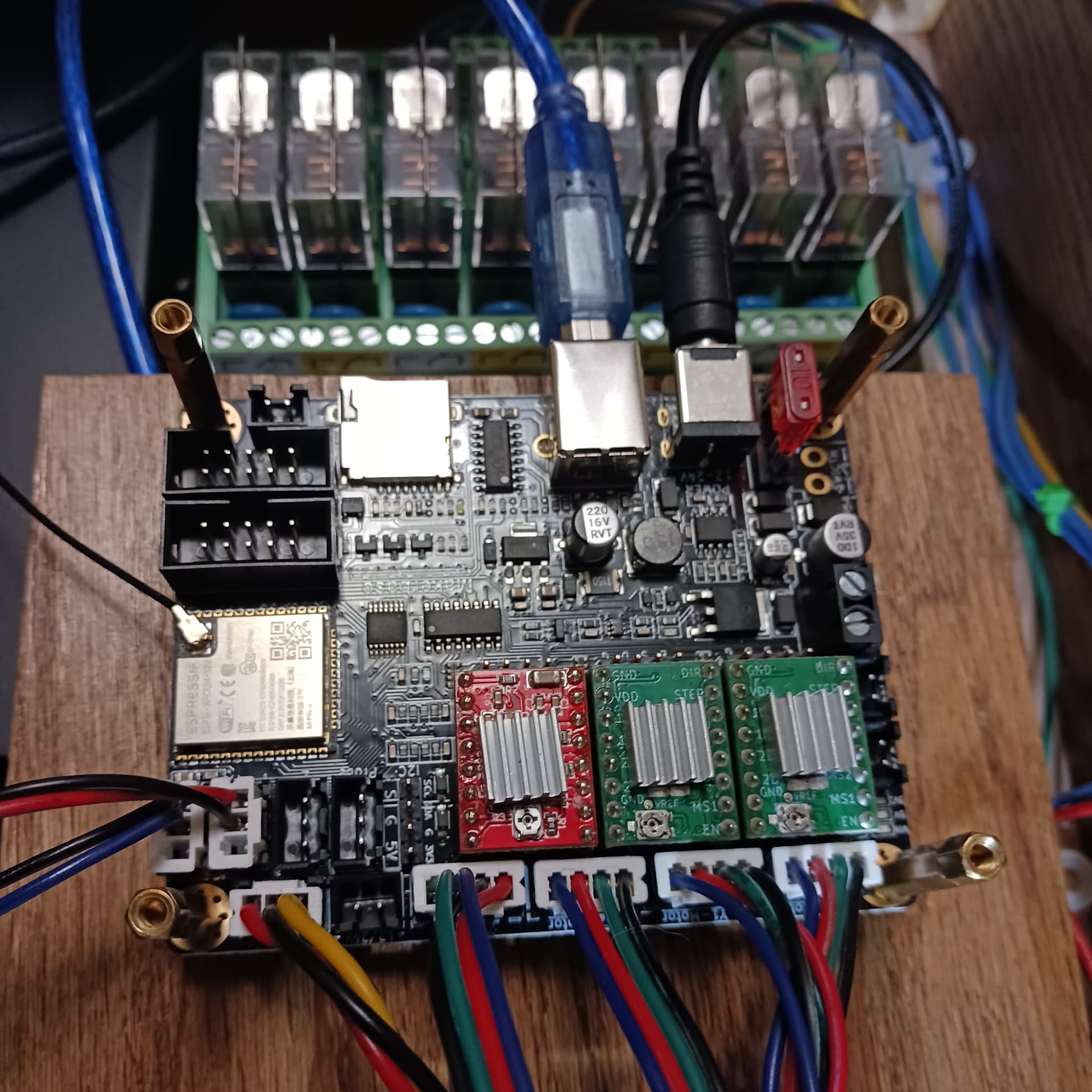
Rich, ( AKA- LA HOBBY GUY) was the first one to reply with help. Rich told me how to change a lot stuff “in” the DLC32 controller itself, which I didn’t know you could do. After I made the needed changes, everything started working right. I am having trouble with my Z stepper. I have everything in L.B. and the controller set correctly and that leaves checking the wiring going to the stepper. I think that I’m going to find that I miswired the A+ & A- with the B+ & B-. Maybe
crossed an A with a B. I’ll know later tonight.
Randy
What all did Rich part with on the knowledge as I am about to do one of those on my router…
Hello John: Really and truly it is easy !
#1 - Click on edit file at top of L.B.
#2 - Go down the list and click machine settings.
#3 - In machine settings, click on “outputs setup”
Clicking “outputs setup” puts you inside the DLC controller. I’m using the DLC32-V2.1. Now don’t change anything that you don’t know what it is !! The first thing you need to do is click save to file and save the factory settings. This is so you can reload the original settings if you mess up. I still have that 5 year old temptations of, “whats this do and click”, oops, not the right thing to do !
Going down the list in outputs setup, you will see all the settings for all the
axis. My DLC 32 has 7 settings under each axis. Go down the list under the Xs list and you will see at the bottom, “X” max travel". That is the X working size. Now do the same for your Y & Z work area. I also reset my travel speeds for my needs. ( I set my Z travel at 200 mm/m because my Z travel is lifting my heavy laser module a total of 9-1/2" above my deck. So I want it going up and down nice and slow.) Look at all the settings closely and set them to what “your” system will need.
Rich told me that the DLC boards normally came with a working area set at 400 x 400mm or so. Mine was set at 450 x 450mm. It appears that a lot of store bought lasers for hobby are around 400x400mm in working size. That’s why DLC sets their boards at 400 or so.
Anyway, that’s all there is to it. Have fun and keep us updated on your project when you start it.
Randy
OOPS !!! I forgot to tell you to click “write” to write your new commands to the DLC board.