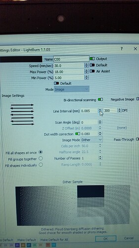
Can anyone tell me what and how the " dot width correction " is used. I am not fully understanding it ? It is located in the cut set editor.
Not seeing it…
What kind of laser do you own? ‘Chinese’ is kind of a blanket term.
![]()
I believe its an Orion Motor Tech. But the setting I am asking about is a Light burn setting.
It is also a 60 watt Co2 with a rudia controller
What I meant is I’m not seeing the ‘dot width correction’ in any of my cut/edit windows.
Screen shot?
![]()
you can see ‘dot width correction’ only if you import an image, and me either don’t know what is it
It’s a new setting for images that is used to compensate for the fact that your beam has width.
If you tell LightBurn to dither an image. On a 50% grey bit, it produces alternating on/off short line segments, like this:
If you draw the width of the beam, it looks more like this:
If you look at that 2nd image, the gaps between the lines are shorter now than the lines themselves, because of the shape of the beam. ‘Dot Correction’ is the total amount to shorten the line, to account for the dot size of the laser. With the proper ‘Dot Correction’ amount, the above output would look like this:
The number should always be smaller than whatever you’re using as your interval setting. The valid range is from 0 to your interval value.
Can’t do negative numbers?
That would make the lines longer, making the inaccuracy worse. No, you can’t. ![]()
Thanks for the Explanation Oz.
I noticed that it could make a big difference on some projects I did but did not understand why. Thanks for always responding and improving the software.
Hello Oz-
The prob is burn energy is constant from one beam radius INSIDE the start point, not at the start point, to one radius OUTSIDE, and a gradient within. The line will fade or disappear anywhere in the gradient area. So this compensation should have both a positive and negative number.
I’ve moving into calibration charts and concluding this is going to be a much more effective, automated approach. It’s awesome
You’re using it for wood, I’m using it for things like anodized or painted surfaces, where the substrate doesn’t darken, but is simply removed if there’s enough power, and not removed if there isn’t.
I very, very rarely see material that is under-burned, and nearly always see material that is over-burned, because people use too high a DPI, and put their shading dots too close together. I’m also not likely to attempt a discussion of gaussian distribution curves with the average housewife making cake toppers. ![]()
This is the result when used on scratch paper:
(left is uncorrected, right is corrected)
Right, that’s threshold vs gradient responses. Well familiar.
But the threshold which removed paint or fuses cermark/moly dry lube/norton tile can be anywhere in that gradient zone- including inside the start point.
“I very, very rarely see material that is under-burned, and nearly always see material that is over-burned, because people use too high a DPI, and put their shading dots too close together.”
Oh lol that is SUCH an easy trap to get into when you’re learning, because initially it looks like you’re improving the quality of image. Which you are, but ONLY because it’s a workaround for LB’s current square-pixel limitation (this is true for any laser). That workaround will dramatically improve the resolution and shading on light tones, but comes with an increasing rate of dot collision on darker tones and then burns out on darker areas, then people start shifting their image brightness up to just avoid the darkest tones, and get trapped.
The trick here is in evaluating the response with objective methods, rather than eyeballing it. Do you have a method yet? I’m doing a writeup on something that would work objectively
That looks real good. Your right a lot of people use way to high DPI . I have used low dpi for some of my wood . Anywhere from 96
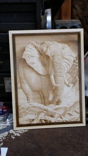
to 500 dpi depending on what I do. Play with wood, ceramic tiles, painted canvas, leather, fabric and rocks. I have even got pretty decent etching on steel with yellow baby mustard. Here is a elephant I did on wood.
That’s really cool. Any plans to accommodate for asymmetric focus dots? I see different engraving characteristics horizontally vs vertically due to the asymmetry. I end up often scanning diagonally to split the difference.
To be honest with you I really no ziltch about asymmetric dots. But I will take your advice and try scanning diagonally on my next project with the new compound lens I have . Would you suggest 45 degrees ?
Sorry, my comment wasn’t meant as advice. I just had not known about this feature and was commenting on it.
I don’t think my mitigation strategy should be really relevant to your situation with your OMT laser. I would expect your laser dot to be circular, not asymmetric. Dot Correction, however, might be of value to you, especially if you’re getting overburn scenarios.
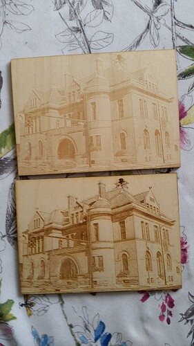
No problem. And yes the dot correction makes a huge difference in the 2 projects I have used it on. The image on the bottom had dot correction.
I understand the question was about Lightburn.
It makes a difference to the ‘reader’ when they look at your photos and realize it’s done on a $100 led from china or a $40k fiber from china. Not knowing what kind of a laser you have for these examples can make them ‘less’ useful.
It might be nice to fix your profile and we won’t annoy you with frivolous questions. Thanks for responding back there…
You have posted some very nice work. I was especially impressed with the elephant. More helpful would have been to clue us in on speed/power and especially what dpi it’s running on these projects. Since you state 96 to 500 as you general range a wide range.
I’m trying to pick your brain here… ![]()
Take care
![]()


